VISHAY SEMICONDUCTOR GSOT03C to GSOT36C Document Number 85824 Rev. 1.7, 21-Apr-08
Summary
Protect valuable electronics with the GSOT series of high-performance two-line ESD protection devices. These components offer superior immunity against both contact and air discharges (up to ± 30 kV) while fitting into a compact SOT23 package. Designed for reliability, they are lead-free and RoHS compliant. This manual provides comprehensive technical specifications, absolute maximum ratings, ordering details, and environmental data necessary for engineers designing robust circuits who require dependable ESD protection solutions.
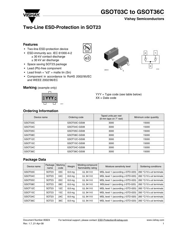
Page 1 Text Content
GSOT03C to GSOT36C
Vishay Semiconductors
Two-Line ESD-Protection in SOT23
Features Two-line ESD-protection device ESD-immunity acc. IEC 61000-4-2 ± 30 k V contact discharge
± 30 k V air discharge Space saving SOT23 package Lead (Pb)-free component Lead finish = "e3" = matte tin (Sn) Component in accordance to Ro HS 2002/95/EC and WEEE 2002/96/EC
Marking (example only)
YYY = Type code (see table below) YYYX XX = Date code
Ordering Information
Taped units per reel
Device name Ordering code Minimum order quantity
(8 mm tape on 7" reel)
GSOT03C GSOT03C-GS08
GSOT04C GSOT04C-GS08 GSOT05C GSOT05C-GS08 GSOT08C GSOT08C-GS08
GSOT12C GSOT12C-GS08 GSOT15C GSOT15C-GS08 GSOT24C GSOT24C-GS08
GSOT36C GSOT36C-GS08
Package Data
Package Marking Molding compound
Device name Weight Moisture sensitivity level Soldering conditions
name code flammability rating
GSOT03C SOT23 03C 8.8 mg UL 94 V-0 MSL level 1 (according J-STD-020) 260 °C/10 s at terminals
GSOT04C SOT23 04C 8.8 mg UL 94 V-0 MSL level 1 (according J-STD-020) 260 °C/10 s at terminals GSOT05C SOT23 05C 8.8 mg UL 94 V-0 MSL level 1 (according J-STD-020) 260 °C/10 s at terminals GSOT08C SOT23 08C 8.8 mg UL 94 V-0 MSLlevel 1 (according J-STD-020) 260 °C/10 s at terminals
GSOT12C SOT23 12C 8.8 mg UL 94 V-0 MSL level 1 (according J-STD-020) 260 °C/10 s at terminals GSOT15C SOT23 15C 8.8 mg UL 94 V-0 MSL level 1 (according J-STD-020) 260 °C/10 s at terminals
GSOT24C SOT23 24C 8.8 mg UL 94 V-0 MSL level 1 (according J-STD-020) 260 °C/10 s at terminals GSOT36C SOT23 36C 8.8 mg UL 94 V-0 MSL level 1 (according J-STD-020) 260 °C/10 s at terminals
Document Number 85824 For technical support, please contact: [email protected] www.vishay.com Rev. 1.7, 21-Apr-08
Page Summary Contents For VISHAY SEMICONDUCTOR GSOT03C to GSOT36C Document Number 85824 Rev. 1.7, 21-Apr-08
Manual Details
| Brand | Vishay |
|---|---|
| Pages | 13 |
| File Size | 195.44 KB |
| Published | June 05, 2026 |
Enter the captcha to get the download link:

Frequently Asked Questions
What levels of ESD immunity do these devices provide?
The devices offer protection against contact and air discharge up to ± 30 kV, per IEC 61000-4-2 standards.
Are these components compliant with current environmental regulations?
Yes, they are Pb-free components that comply with RoHS 2002/95/EC and WEEE 2002/96/EC directives.
What is the recommended soldering temperature cycle?
The specified soldering condition is 260 °C for 10 seconds at the terminals.
What are the operational temperature limits?
The acceptable operating junction temperature range is from -40 to +125 °C.