Vishay SMF5V0A to SMF52A Data Sheet / Manual
Summary
These low-profile, surface mount ESD protection diodes are engineered to safeguard critical data lines in networking applications against damaging transient voltage surges (ESD/EFT). The accompanying technical manual provides comprehensive documentation covering electrical characteristics, thermal performance ratings, durability metrics, and compliance details required for design integration. This product is ideal for electronics engineers designing robust and reliable equipment that demands industry-leading protection and high operational standards.
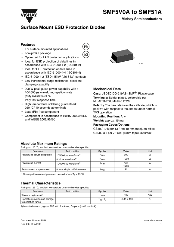
Page 1 Text Content
SMF5V0A to SMF51A Vishay Semiconductors
Surface Mount ESD Protection Diodes
Features For surface mounted applications Low-profile package
Optimized for LAN protection applications Ideal for ESD protection of data lines in accordance with IEC 61000-4-2 (IEC801-2) Ideal for EFT protection of data lines in accordance with IEC 61000-4-4 (IEC801-4) IEC 61000-4-2 (ESD) 15 k V (air) 8 k V (contact) Low incremental surge resistance, excellent clamping capability 200 W peak pulse power capability with a Mechanical Data 10/1000 µs waveform, repetition rate
Case: JEDEC DO-219AB (SMF®) Plastic case
(duty cycle): 0.01 %
Terminals: Solder plated, solderable per
Very fast response time
MIL-STD-750, Method 2026
High temperature soldering guaranteed:
Polarity:The band denotes the cathode, which is
°C/ 10 seconds at terminals
positive with respect to the anode under normal
Lead (Pb)-free component TVS operation Component in accordance to Ro HS 2002/95/EC Mounting Position: Any and WEEE 2002/96/EC
Weight: approx. 15 mg Packaging Codes/Options: GS18 / 10 k per 13 " reel (8 mm tape), 50 k/box GS08 / 3 k per 7 " reel (8 mm tape), 30 k/box
Absolute Maximum Ratings Ratings at 25 °C, ambient temperature unless otherwise specified
Parameter Test condition Symbol Value Unit
Peak pulse power dissipation PPPM
10/1000 µs waveform1)
8/20 µs waveform1)
Peak pulse current IPPM next
10/1000 µs waveform1)
Table
Peak forward surge current 8.3 ms single half sine-wave IFSM 1) Non-repetitive current pulse and derated above TA = 25
Thermal Characteristics Ratings at 25 °C, ambient temperature unless otherwise specified
Parameter Test condition Symbol Value Unit
Rth JA K/W
Thermal resistance2) Operation junction and storage Tstg, TJ - 55 to + 150 °C temperature range
2) Mounted on epoxy glass PCB with 3 x 3 mm, Cu pads ( ≥ 40 µm thick)
Document Number 85811 www.vishay.com Rev. 2.0, 29-Apr-05
Page Summary Contents For Vishay SMF5V0A to SMF52A Data Sheet / Manual
Manual Details
| Brand | Vishay |
|---|---|
| Pages | 7 |
| File Size | 218.19 KB |
| Published | June 03, 2026 |
Enter the captcha to get the download link:

Frequently Asked Questions
What types of electromagnetic interference is this diode optimized for?
It is ideal for ESD protection following IEC 61000-4-2 and EFT protection in accordance with IEC 61000-4-4.
What is the peak pulse power dissipation rating at standard test conditions?
The device can handle 200 W of peak pulse power with a 10/1000 µs waveform.
Is this component compliant with current environmental standards regarding heavy metals?
Yes, it is explicitly listed as a Lead (Pb)-free component and complies with both RoHS and WEEE directives.
Are there specific requirements for ensuring proper performance in an assembly?
All operating parameters must be validated by the customer for their specific application; misuse voids liability.