Vishay Semiconductor New TSOP61.. Product Specifications
Summary
The TSOP61 series are advanced, miniaturized SMD-IR receiver modules designed for reliable operation in remote control systems. Featuring an integrated photo detector and preamplifier, they offer high data rates and exceptional performance with short burst transmissions. This manual provides comprehensive technical specifications, electrical characteristics, and application guides necessary for engineers developing precise infrared communication and sensing solutions.
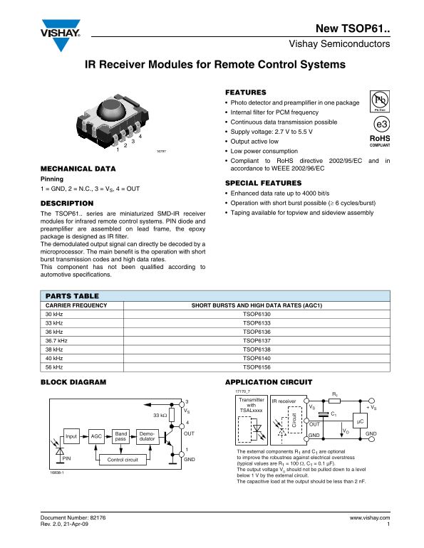
Page 1 Text Content
New TSOP61.. Vishay Semiconductors
IR Receiver Modules for Remote Control Systems
FEATURES Photo detector and preamplifier in one package Internal filter for PCM frequency Continuous data transmission possible Supply voltage: 2.7 V to 5.5 V Output active low Low power consumption Compliant to Ro HS directive 2002/95/EC and in MECHANICAL DATA accordance to WEEE 2002/96/EC
Pinning
SPECIAL FEATURES
1 = GND, 2 = N.C., 3 = VS, 4 = OUT
Enhanced data rate up to 4000 bit/s DESCRIPTION Operation with short burst possible (≥ 6 cycles/burst) The TSOP61.. series are miniaturized SMD-IR receiver Taping available for topview and sideview assembly
modules for infrared remote control systems. PIN diode and preamplifier are assembled on lead frame, the epoxy package is designed as IR filter. The demodulated output signal can directly be decoded by a microprocessor. The main benefit is the operation with short burst transmission codes and high data rates. This component has not been qualified according to automotive specifications.
irc ui
PARTS TABLE CARRIER FREQUENCY SHORT BURSTS AND HIGH DATA RATES (AGC1) 30 k Hz TSOP6130 33 k Hz TSOP6133 36 k Hz TSOP6136 36.7 k Hz TSOP6137 38 k Hz TSOP6138 40 k Hz TSOP6140 56 k Hz TSOP6156
BLOCK DIAGRAM APPLICATION CIRCUIT
Transmitter
IR receiver
VS + VS
VS TSALxxxx
Band Demo- OUT GND
Input AGC GND
pass dulator
The external components R1 and C1 are optional to improve the robustnes against electrical overstress
Control circuit PIN GND
(typical values are R1 = 100 Ω, C1 = 0.1 µF). The output voltage VO should not be pulled down to a level
below 1 V by the external circuit. The capacitive load at the output should be less than 2 n F.
Document Number: 82176 www.vishay.com Rev. 2.0, 21-Apr-09
Page Summary Contents For Vishay Semiconductor New TSOP61.. Product Specifications
Manual Details
| Brand | Vishay |
|---|---|
| Pages | 12 |
| File Size | 384.02 KB |
| Published | June 03, 2026 |
Enter the captcha to get the download link:
