Vishay Semiconductor VESD05A4A-HS4 Specifications and User Guide
Summary
This ultra-compact quad ESD Protection Diode Array offers robust safeguarding for multiple electronic data lines against severe transient voltage spikes and electrostatic discharge events. Engineered for reliable performance, it maintains low leakage current while handling high peak pulse currents typical of harsh environments. This comprehensive technical manual is essential reading for electronics designers and engineers, providing detailed electrical characteristics, application guidelines, compliance testing results (IEC 61000-4-2), and optimal integration procedures to ensure system reliability.
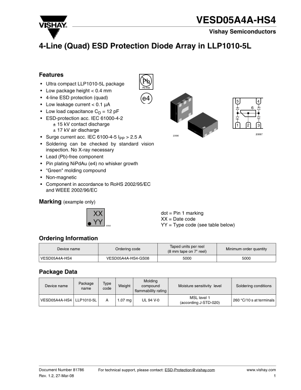
Page 1 Text Content
VESD05A4A-HS4 Vishay Semiconductors
4-Line (Quad) ESD Protection Diode Array in LLP1010-5L
Features Ultra compact LLP1010-5L package Low package height < 0.4 mm 4-line ESD protection (quad) e4 Low leakage current < 0.1 µA Low load capacitance CD = 12 p F ESD-protection acc. IEC 61000-4-2 ± 15 k V contact discharge ± 17 k V air discharge Surge current acc. IEC 6100-4-5 IPP > 2.5 A Soldering can be checked by standard vision inspection. No X-ray necessary Lead (Pb)-free component Pin plating Ni Pd Au (e4) no whisker growth "Green" molding compound Non-magnetic Component in accordance to Ro HS 2002/95/EC and WEEE 2002/96/EC
Marking (example only)
XX dot = Pin 1 marking XX = Date code
YY = Type code (see table below)
Ordering Information
Taped units per reel
Device name Ordering code Minimum order quantity
(8 mm tape on 7" reel)
VESD05A4A-HS4 VESD05A4A-HS4-GS08
Package Data
Molding
Package Type
Device name Weight compound Moisture sensitivity level Soldering conditions
name code
flammability rating
MSL level 1
VESD05A4A-HS4 LLP1010-5L 1.07 mg UL 94 V-0 260 °C/10 s at terminals
(according J-STD-020)
Document Number 81786 For technical support, please contact: [email protected] www.vishay.com Rev. 1.2, 27-Mar-08
Page Summary Contents For Vishay Semiconductor VESD05A4A-HS4 Specifications and User Guide
Manual Details
| Brand | Vishay |
|---|---|
| Pages | 9 |
| File Size | 172.64 KB |
| Published | May 31, 2026 |
Enter the captcha to get the download link:

Frequently Asked Questions
What is the maximum operating temperature range?
The junction operating temperature (TJ) ranges from -40 to +125 °C.
How many lines can be protected using this device?
It can protect up to four signal- or data-lines (L1 - L4).
Is X-ray needed for soldering inspection?
No, standard vision inspection is sufficient; no X-ray is necessary.
What type of environmental protection does it offer?
It offers ESD protection against IEC 61000-4-2 (± 15 kV contact) and airborne discharge.