Vishay Semiconductor LH1522AB AAC AACTR Specifications and User Guide
Summary
The LH1522 is a robust, dual-channel Solid State Relay ideal for high-reliability industrial control and telecom applications. Featuring galvanic isolation up to 5300 V RMS, this relay provides clean, bounce-free switching combined with integrated current limit protection, making it a reliable replacement for traditional electromechanical devices. This manual serves as a comprehensive technical guide, detailing the full electrical characteristics, absolute ratings, and best practices required for integrating the SSR into complex control systems.
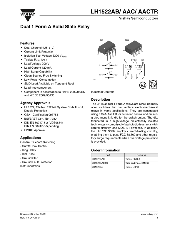
Page 1 Text Content
LH1522AB/ AAC/ AACTR
Vishay Semiconductors
Dual 1 Form A Solid State Relay
DIP SMD
Features Dual Channel (LH1510) Current Limit Protection Isolation Test Voltage 5300 VRMS Typical RON 10 Ω S1' S2'S2S1 Load Voltage 200 V
Load Current 120 m A High Surge Capability
Clean Bounce Free Switching
Low Power Consumption i179034
SMD Lead Available on Tape and Reel Pb
e3 Lead-free component Pb-free
Component in accordance to Ro HS 2002/95/EC Industrial Controls and WEEE 2002/96/EC
Description
Agency Approvals
The LH1522 dual 1 Form A relays are SPST normally UL1577, File No. E52744 System Code H or J, open switches that can replace electromechanical Double Protection relays in many applications. They are constructed CSA - Certification 093751 using a Ga AIAs LED for actuation control and an inte- grated monolithic die for the switch output. The die,
BSI/BABT Cert. No. 7980
fabricated in a high-voltage dielectrically isolated
DIN EN 60747-5-2 (VDE0884)
technology is comprised of a photodiode array, switch
DIN EN 60747-5-5 pending
control circuitry, and MOSFET switches. In addition,
FIMKO Approval
the LH1522 SSRs employ current-limiting circuitry, enabling them to pass FCC 68.302 and other regula-
Applications tory surge requirements when overvoltage protection
General Telecom Switching is provided.
- On/off Hook Control - Ring Delay Order Information - Dial Pulse
Part Remarks
- Ground Start
LH1522AAC Tubes, SMD-8
- Ground Fault Protection
LH1522AACTR Tape and Reel, SMD-8
Instrumentation
LH1522AB Tubes, DIP-8
Document Number 83821 www.vishay.com Rev. 1.3, 26-Oct-04
Page Summary Contents For Vishay Semiconductor LH1522AB AAC AACTR Specifications and User Guide
Manual Details
| Brand | Vishay |
|---|---|
| Pages | 9 |
| File Size | 188.57 KB |
| Published | June 15, 2026 |
Enter the captcha to get the download link:

Frequently Asked Questions
What is the recommended ambient temperature range for operation?
The operational temperature range for the device is from -40°C to +85°C.
How is insulation and voltage safety managed with this relay?
It features a high isolation test voltage of 5300 V RMS pole-to-pole.
Does this solid state relay offer surge protection?
Yes, it employs current-limiting circuitry enabling it to pass FCC regulations when overvoltage protection is provided.
What are the typical ON and OFF resistances?
The nominal ON-resistance (R) is typically 10 Ω, and the typical OFF-resistance is generally 5000 GΩ.