LINEAR LT1680 High-Power DC-DC Step-Up Controller Data Sheet User Manual
Summary
The LT1680 is a powerful, current-mode switching DC/DC step-up controller designed specifically for robust boost converter topologies. Featuring high voltage support up to 60V and programmable average current limiting, this IC offers advanced protection and synchronization capabilities (up to 200kHz), making it ideal for demanding applications. This technical manual provides comprehensive specifications, electrical characteristics, and detailed application guidance for integrating the LT1680 into industrial control systems, automotive equipment, and battery back-up solutions requiring stable, high-power power regulation.
Page 1 Text Content
查询LT1680供应商
LT1680
High Power DC/DC Step-Up Controller
FEATURES DESCRIPTION High Voltage: Operation Up to 60V Max The LT®1680 is a high power, current mode switching High Current: N-Channel Drive Handles Up to power supply controller optimized for boost topologies. 10,000p F Gate Capacitance The IC drives N-channel MOSFET switches for DC/DC Programmable Average Current Limiting converters in applications up to 60V input. A high current 5V Reference Output with 10m A External gate drive output handles up to 10,000p F gate capaci- tance, enabling the construction of high power DC/DC
Loading Capability
converters. Current sense common mode range up to 60V
Fixed Frequency Current Mode Operation
allows current sensing to be referenced to the input
Oscillator Synchronizable Up to 200k Hz
supply, eliminating the need for sense blanking circuits.
Undervoltage Lockout with Hysteresis Programmable Start Inhibit for Power Supply The LT1680 incorporates programmable average current Sequencing and Protection limiting allowing accurate limiting of DC current in the User Adjustable Slope Compensation magnetics, independent of ripple current . User adjustable
slope compensation provides stable operation at duty cycles up to 90%.
APPLICATIONS
The LT1680 operating frequency is programmable and
High Power Single Board Systems can be synchronized up to 200k Hz. Minimum off-time Distributed Power Converters operation provides switch protection. The IC also incorpo-
EF FI CI EN CY
Industrial Control Systems rates a soft start feature that is gated by both shutdown
Lead-Acid Battery Back-Up Systems and undervoltage lockout conditions. Automotive and Heavy Equipment , LTC and LT are registered trademarks of Linear Technology Corporation.
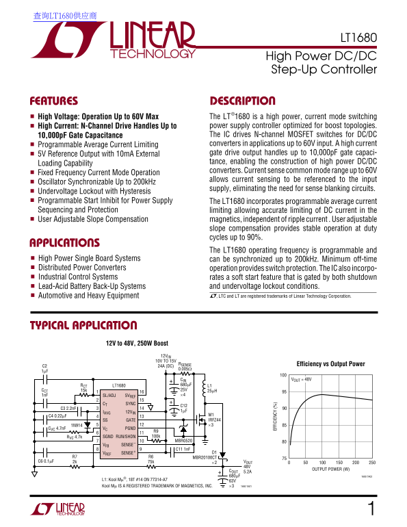
TYPICAL APPLICATION
12V to 48V, 250W Boost
12VIN 10V TO 15V
RSENSE Efficiency vs Output Power
C2 24A (DC)
CIN VOUT = 48V
RCT LT1680 680µF L1 CCT 15k 25V 25µH 1n F SL/ADJ 5VREF ×4
CT SYNC
IAVG 12VIN 1µF
C4 0.22µF M1 SS GATE IRFZ44 1N914 ×3
CVC 4.7n F VC PGND
R9 RVC 4.7k SGND RUN/SHDN 100k
MBR0520
VFB SENSE–
VREF SENSE+ D1
R7 R6 MBR20100CT
C6 0.1µF 2k 75k VOUT
OUTPUT POWER (W)
COUT 5.2A 680µF 1680 TA02
L1: Kool Mµ®, 18T #14 ON 77314-A7 63V
Kool Mµ IS A REGISTERED TRADEMARK OF MAGNETICS, INC. ×3 1680 TA01
Page Summary Contents For LINEAR LT1680 High-Power DC-DC Step-Up Controller Data Sheet User Manual
Manual Details
| Brand | Linear |
|---|---|
| Pages | 16 |
| File Size | 307.92 KB |
| Published | June 03, 2026 |
Enter the captcha to get the download link:

Frequently Asked Questions
What voltage range is the LT1680 optimized for?
It is a high power controller optimized for boost topologies, capable of operating up to 60V input.
How can I synchronize or control the switching frequency?
The oscillator is synchronizable up to 200kHz, and the frequency itself is programmable.
What protection mechanisms are provided by the chip?
It includes Undervoltage Lockout with Hysteresis, a soft start feature, and programmable average current limiting.