# A B C D E F G H I J K L M N O P Q R S T U V W X Y Z

RICOH R1286K SERIES 2ch DCDC (Step Up DC-DC and Inverting DC-DC) Data Manual

Summary

This high-efficiency dual DC/DC converter is engineered specifically for powering demanding applications, such as AMOLED displays and portable electronics, by generating both boosted positive (step-up) and adjustable negative (inverting) voltages. Featuring a single-wire interface (S-Wire) for dynamic voltage control and comprehensive protection circuits like UVLO and thermal shutdown, it ensures reliable power delivery. This resource provides detailed technical specifications, selection guides, and operational diagrams necessary for engineers integrating stable, bi-polar power solutions into complex electronic designs.
📄 Preview PAGE OF 25

Page 1 Text Content

R1286K SERIES

2ch DCDC (Step Up DC/DC and Inverting DC/DC)

NO.EA-283-120228

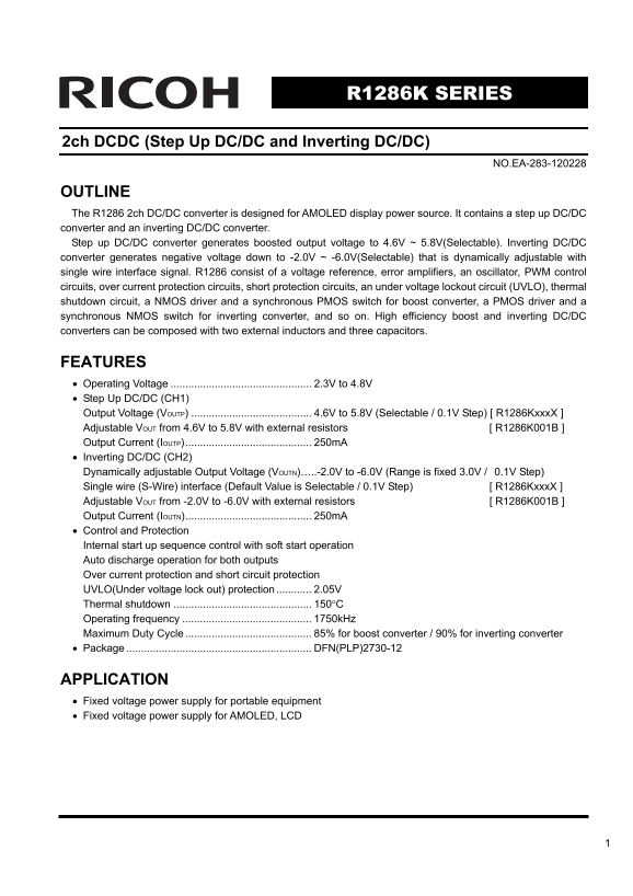
OUTLINE The R1286 2ch DC/DC converter is designed for AMOLED display power source. It contains a step up DC/DC converter and an inverting DC/DC converter. Step up DC/DC converter generates boosted output voltage to 4.6V ~ 5.8V(Selectable). Inverting DC/DC converter generates negative voltage down to -2.0V ~ -6.0V(Selectable) that is dynamically adjustable with single wire interface signal. R1286 consist of a voltage reference, error amplifiers, an oscillator, PWM control circuits, over current protection circuits, short protection circuits, an under voltage lockout circuit (UVLO), thermal shutdown circuit, a NMOS driver and a synchronous PMOS switch for boost converter, a PMOS driver and a synchronous NMOS switch for inverting converter, and so on. High efficiency boost and inverting DC/DC converters can be composed with two external inductors and three capacitors.

FEATURES • Operating Voltage 2.3V to 4.8V • Step Up DC/DC (CH1) Output Voltage (VOUTP) 4.6V to 5.8V (Selectable / 0.1V Step) [ R1286Kxxx X ] Adjustable VOUT from 4.6V to 5.8V with external resistors [ R1286K001B ] Output Current (IOUTP)........................................... 250m A • Inverting DC/DC (CH2) Dynamically adjustable Output Voltage (VOUTN)…..-2.0V to -6.0V (Range is fixed 3.0V / 0.1V Step) Single wire (S-Wire) interface (Default Value is Selectable / 0.1V Step) [ R1286Kxxx X ] Adjustable VOUT from -2.0V to -6.0V with external resistors [ R1286K001B ] Output Current (IOUTN)........................................... 250m A • Control and Protection Internal start up sequence control with soft start operation Auto discharge operation for both outputs Over current protection and short circuit protection UVLO(Under voltage lock out) protection 2.05V Thermal shutdown 150°C Operating frequency 1750k Hz Maximum Duty Cycle 85% for boost converter / 90% for inverting converter • Package DFN(PLP)2730-12

APPLICATION • Fixed voltage power supply for portable equipment • Fixed voltage power supply for AMOLED, LCD

Page Summary Contents For RICOH R1286K SERIES 2ch DCDC (Step Up DC-DC and Inverting DC-DC) Data Manual

Page 1 R1286K SERIES 2ch DCDC (Step Up DC/DC and Inverting DC/DC) NO.EA-283-120228 OUTLINE The R1286 2ch DC/DC converter is designed for AMOLED display power source. It contains a step up DC/DC converter and...
Page 2 BLOCK DIAGRAM ●R1286Kxxx A/C~G Current Current Sense Sense Maxduty Limit Limit PGND PWM PWM Control Control Timer Short Protect Discharge Discharge VOUTN Control VOUTP R S Control VOUTNS VOUTPS Slope ...
Page 3 Current Current Sense Sense Maxduty Limit Limit PGND PWM PWM Control Control Timer Short Protect Discharge Discharge VOUTN R S VOUTP Control Control Osc VFBPVFBN Slope VREF Soft Start2 Soft Start1 Cur...
Page 4 SELECTION GUIDE The inverting output voltage (VOUTN), the positive output voltage (VOUTP) and the versions of the inverting output voltage are user-selectable options. Product Name Package Quantity pe...
Page 5 ・voltage combination list. xxx VOUTP VONDEF External 001 External resistors resistors PIN CONFIGURATION ● DFN(PLP)2730-12 Top Bottom
Page 6 PIN DESCRIPTION • R1286Kxxx A/C~G Pin No. Symbol Description 1 VOUTNS Feed Back Pin for Inverting DC/DC 2 VOUTN Outout Pin for Inverting DC/DC 3 LXN Switching Pin for Inverting DC/DC 4 PVCC Power Inpu...
Page 7 ABSOLUTE MAXIMUM RATINGS (GND=PGND=0V) Symbol Item Rating Unit VCC VCC / PVCC Pin Voltage -0.3 to 6.0 V VCE CE Pin Voltage -0.3 to 6.0 V VLXP LXP Pin Voltage -0.3 to 6.5 V VOUTP(S) VOUTP Pin Voltage -...
Page 8 ELECTRICAL CHARACTERISTICS (Ta=25ºC) Symbol Item Conditions Min. Typ. Max. Unit VCC Operating Input Voltage 2.3 4.8 V ICC VCC Consumption Current (at no switching) VCC=4.8V 1.2 m A Istandby Standby Cu...
Page 9 Symbol Item Conditions Min. Typ. Max. Unit ■Inverting DC/DC ∆VOUTN VOUTN Voltage 2.9V VCC 4.2V, /∆IOUT Load Regulation 10m A IOUT 100m A ±5 m V VCC=2.9V ↔ 3.4V, ∆VOUTN_TR VOUTN Voltage TR=TF=50μs ±15 ...
Page 10 TIMING CHART • SEQUENCE with S-Wire control for VOUTN(R1286Kxxx A/C~G) CE pin VOUTP Output Voltage VOUTN t SS tvo_off toff_dly shutdown default value shutdown softstart ・Softstart VOUTP rises up first...
Page 11 • VOUTN Variable Table The adjusted value setting command are operated with S-Wire input (pulse count) that is shown in Table.1. Table.1 VOUTN Variable Table ( 31 steps ) BIT (pulse count) VOUTN BIT (...
Page 12 TECHNICAL NOTES ●R1286Kxxx A/C~G VOUTN VOUTNS TST EN control VOUTN CE S-Wire control LXN VOUTPS VOUTP VOUTPPVCC VCC LXP GND PGND L1 VLF302510M-4R7M(TDK) VLF3010S-4R7M(TDK) L2 VLF4012S-4R7M (TDK) NR401...
Page 13 ⋅ Set a ceramic 4.7μF or more capacitor between VCC and GND as C1. ⋅ Set a ceramic 4.7μF or more capacitor between VOUTP and GND, and between VOUTN and GND for each as C2 and C3. ⋅ Set a ceramic 0.1μF...
Page 14 ⋅ Over Current Protection and Short Protection Circuit Timer The over current protection circuit supervises the peak current of the coil (The current passing through NMOS transistor of CH1 and PMOS tr...
Page 15 Operation of Step-up DC/DC Converter and Output Current <Basic Circuit> IL2 Inductor Pch Tr VIN VOUT CL Nch Tr <Current through L> Discontinuous Mode Continuous Mode IL ILxmax IL ILxmax ILxmin ILxmin ...
Page 16 In the continuous mode, the current variation of IL1 and IL2 are same, therefore VIN × ton / L = (VOUT - VIN) × toff / L ..................................................................................
Page 17 Operation of Inverting DC/DC Converter and Output Current <Basic Circuit> Pch Tr Nch Tr IOUT VOUT IL1 IL2 Inductor <Current through L> Discontinuous Mode Continuous Mode ILxmax IL IL ILxmax ILxmin ILx...
Page 18 In the continuous mode, the current variation of IL1 and IL2 are same, therefore VIN × ton / L = VOUT × toff / L ..........................................................................................
Page 19 ffi ci en cy [V [V ■R1286Kxxx X Typical Characteristics 1) Output voltage vs. Output Current R1286Kxxx X(VOUTP= 4.6V) R1286Kxxx X(VOUTP= 5.4V) Ta=25°C Ta=25°C 4.56 Vin= 4.8 V 5.36 Vin= 4.8 V 4.54 Vin=...
Page 20 ffi ci en cy R1286Kxxx X(VOUTP=5.8V VOUTN= -6.0V) R1285L00x B(Vout N= -4.9V) Ta=25°C Vin= 4.2 V Vin= 3.7 V Vin= 2.9 V IOUT N [m A] 3) Turn-on/Turn-off Wave Form by CE CH1=CE CH1=CE CH2=VOUTP CH2=VOUTP...
Page 21 4)  VOUTN Wave Form with S-Wire control R1286K002A(-4.9V to -2.4V) R1286K002A(-2.4V to -4.9V) Ta=25°C Ta=25°C IOUTP=IOUTN=0m A IOUTP=IOUTN=0m A pulse= 31 count pulse= 6 count CH1=CE CH1=CE CH2=VOUTN C...
Page 22 TN [V ]  TN [V ]  LO [V ]  7) UVLO Voltage VS. Temperature 8) VOUTP Voltage VS. Temperature R1286Kxxx X R1286K002X UVLO Release Ta [°C] TN [V ]  Ta [°C] TP [V ]  9) VOUTN Voltage VS. Temperature R1286...
Page 23 FO 1A [k z] LI LX [A ]  FB [V ]  10) VFBN Voltage VS. Temperature 11) VREF Voltage VS. Temperature Ta [°C] Ta [°C] LI LX [A ]  12) LXP Current Limit VS. Temperature 13) LXN Current Limit VS. Temperatu...
Page 24 TS [m s] TS [m s] ax du ty ]  15) Maxduty1 VS. Temperature 16) Maxduty2 VS. Temperature R1286Kxxx X R1286Kxxx X TS [m s] ax du ty ]  Ta [°C] Ta [°C] 17) CH1 Soft-Start Time VS. Temperature 18) CH2 Sof...
Page 25 1. The products and the product specifications described in this document are subject to change or discontinuation of production without notice for reasons such as improvement. Therefore, before decid...

Manual Details

Brand Ricoh
Pages 25
File Size 857.96 KB
Published June 01, 2026
84 views

Enter the captcha to get the download link:

captcha

Frequently Asked Questions

What is the primary application of the R1286 module?

It is designed as a DC/DC converter for generating power sources for AMOLED displays.

How is the negative output voltage (VOUTN) controlled?

The negative voltage can be dynamically adjusted using a Single wire (S-Wire) interface signal.

What protection features are built into this DC/DC converter?

It includes Over current protection, short circuit protection, and Under voltage lock out (UVLO).

How do I adjust the positive output voltage (VOUTP)?

The VOUTP can be adjusted using external resistors or through selectable model variants.