RICOH R1212D Series PWM Step-up DC-DC Controller Data Sheet User Manual
Summary
The R1212D series is a highly versatile, low supply current PWM step-up DC/DC controller designed to build efficient power sources for electronic devices. This manual details its advanced features, including adjustable oscillator frequency (300kHz–1.4MHz), controllable maximum duty cycle, and robust UVLO protection. It offers precise external control over soft start times, making it ideal for engineers designing portable or consumer electronics applications like hand-held equipment power supplies, LCD panels, and general industrial components requiring high efficiency and stability.
Page 1 Text Content
R1212D Series PWM Step-up DC/DC Controller
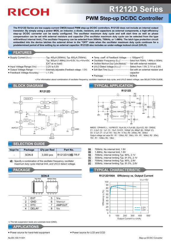
The R1212D Series are low supply current CMOS-based PWM step-up DC/DC controllers. R1212D does not include an internal output transistor. By simply using a power MOS, an inductor, a diode, resistors, and capacitors as external components, a high-efficiency step-up DC/DC converter can be easily configured. The oscillator maximum duty cycle and soft start time as well as phase compensation can be set with external resistors and capacitor (The oscillator maximum duty cycle can be selected from the type with/without internal limit.) The oscillator frequency can be selected from 300k Hz, 700k Hz, or 1.4MHz. The latch type protection circuit embedded into the device latches the external driver in the "OFF" state when the oscillator maximum duty cycle continues for a predetermined period of time setting by an external capacitor. R1212D also includes an under-voltage lockout circuit (UVLO).
FEATURES • Supply Current (IDD1)·······················Typ. 400μA (300k Hz), Typ. 600μA (700k Hz), • Temp. coeff. of Feedback Voltage····· ± 150ppm/°C
Typ. 900μA (1.4MHz) (VIN=5.5V, VDLY=VFB=0V, • Oscillator Frequency (fosc)∗ ············· Select from 700k Hz, 1.4MHz or 300k Hz.
EXT at no load) • Oscillator Maximum Duty Cycle (Maxduty)∗ ···· Set with external resistors • Input Voltage Range (VIN) ··············2.2V to 5.5V • UVLO Detect Voltage (VUVLO)∗ ············· Select from 1.9V, 2.1V or 2.8V. • Output Voltage Range ····················Externally adjustable (Feedback voltage : 1.0V) • Soft Start Time (tstart) ·························· Set with an external resistor and • Feedback Voltage Accuracy ···········± 1.5% capacitor
• Package ········································· SON-8
∗) For information about combination of oscillator frequency, oscillator maximum duty cycle, and UVLO detect voltage, see SELECTION GUIDE.
BLOCK DIAGRAM TYPICAL APPLICATION
Internal VR VIN R3
VREFOUT VREFOUT UVLO VIN EXT NMOS
ff ic ie C4
OSC DELAY VFB C3
EXT GND AMPOUT
PWM Comp
Latch VREFOUT DTC
VREF R5 R6 C7
Error Amp.
AMPOUT NMOS : CPH6415, L : VLP5612T, 10μH (A), 4.7μH (B), 22μH (C), SD : CRS02,
C1 : 2.2μF, C2 : 1μF, C3 : 15μF, C4=C5 : 1000p F (A), 680p F (B), 1500p F (C), C6 : 0.1μF, C7 : 0.1μF, R3 : 1kΩ, R4 : 4.7kΩ, R5 : 240kΩ, R6 : 300kΩ Output voltage set value 5V⋅⋅⋅R1 : 120kΩ, R2 : 30kΩ, 10V⋅⋅⋅R1 : 180kΩ, R2 : 20kΩ, DELAY 15V⋅⋅⋅R1 : 140kΩ, R2 : 10kΩ
SELECTION GUIDE
.0A. : 700k Hz, No internal limit, 1.9V
Halogen Free Package Q'ty per Reel Part No.
.0B. : 1.4MHz, No internal limit, 1.9V
- SON-8 3,000 pcs R1212D10.∗$ -TR-F LO AD
.1A. : 700k Hz, Internal limiting Typ. 90%, 2.1V .1C. : 300k Hz, Internal limiting Typ. 91.5%, 2.1V ∗$ : Specify a combination of the oscillator frequency, oscillator .2A. : 700k Hz, Internal limiting Typ. 90%, 2.8V maximum duty cycle internal limit, and UVLO detect voltage. .2C. : 300k Hz, Internal limiting Typ. 91.5%, 2.8V
PACKAGE TYPICAL CHARACTERISTIC
SON-8 R1212D100A Efficiency vs. Output Current
Bottom View Top View
VOUT=5V
1 EXT VFB 2 GND VREFOUT 3 DTC AMPOUT
4 DELAY VIN
Output Current IOUT(m A)
∗) The tab suspension leads are substrate level (GND).
APPLICATIONS • Power source for hand-held equipment • Power source for LCD and CCD No.EK-109-111001 Step-up DC/DC Converter
Page Summary Contents For RICOH R1212D Series PWM Step-up DC-DC Controller Data Sheet User Manual
Manual Details
| Brand | Ricoh |
|---|---|
| Pages | 2 |
| File Size | 149.50 KB |
| Published | June 04, 2026 |
Enter the captcha to get the download link:

Frequently Asked Questions
What external components are required for operation?
External components include a power MOS, an inductor, a diode, resistors, and capacitors.
How can the oscillator frequency be configured?
The oscillator frequency can be selected from 300kHz, 700kHz, or 1.4MHz.
Does this controller have internal protection features?
Yes, it includes a latch-type protection circuit and an under-voltage lockout (UVLO) circuit.
How is the output voltage adjusted?
The output voltage is externally adjustable using a feedback voltage connection (VFB).
What is the typical supply current at 1.4MHz?
The typical supply current is 900μA when VIN=5.5V and no load.