RICOH R1210N Series 8V Input PWM Step-up DC DC Converter User's Guide
Summary
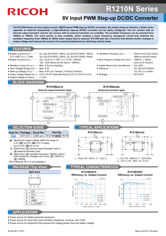
The R1210N Series is a high-efficiency, CMOS-based PWM Step-up DC/DC converter designed for reliable power conversion from up to 8V input. This manual provides comprehensive details on its operation, covering low supply current features, selectable oscillator frequencies (100kHz or 180kHz), and adaptive modes to minimize voltage overshoot/undershoot. It is ideal for engineers designing battery-powered equipment like communication gear, cameras, and other devices that require a stable voltage higher than the source power.
Page 1 Text Content
R1210N Series
8V Input PWM Step-up DC/DC Converter
The R1210N Series are low supply current, CMOS-based PWM step-up DC/DC converters. By simply using an inductor, a diode, and a capacitor as external components, a high-efficiency step-up DC/DC converter can be easily configured. The xx1 version with an internal output transistor and the xx2 version with an external transistor are available. The oscillator frequency can be selected from 100k Hz or 180k Hz. The xx1A version is also available, which contains a basic frequency changeover circuit that switches the oscillator frequency from 100k Hz to 35k Hz when output load is reduced. R1210N also has a function that detects drastic changes in output voltage and reduces the amount of overshoot/undershoot by switching control mode.
FEATURES • Supply Current (IDD1)·············· Typ. 35μA (R1210N301, 100k Hz), Typ. 60μA (R1210N301, 180k Hz) • Oscillator Frequency (fosc) ·············· 100k Hz (xx1A/xx1C/xx2C Version),
(VOUT=SET VOUT × 0.96) Typ. 20μA (R1210N302, 100k Hz), Typ. 25μA (R1210N302, 180k Hz) 180k Hz (xx1D/xx2D Version)
• Supply Current (IDD2)·············· Typ. 10μA (VOUT=SET VOUT+0.5V, 100k Hz) • Basic Frequency Change-over Circuit ···· 100k Hz → 35k Hz Typ. 15μA (Same as the above, 180k Hz) (only xx1A Version) • Standby Current (Istandby) ········ Max. 0.5μA (In standby) • Oscillator Maximum Duty Cycle (Maxduty)····· Typ. 85% • Input Voltage Range (VIN) ······ Max. 8.0V • Efficiency········································ Typ. 88% (R1210N301, • Start-up Voltage (Vstart) ··········· Max. 0.9V (xx1 Version), 0.8V(xx2 Version) VIN=1.8V, IOUT=10m A)
ff ic ie
• Output Voltage Range (VOUT) ··· 2.2V to 6.0V (internally fixed) (2.2V to 3.5V for xx1A) • Package ········································· SOT-23-5 • Output Voltage Accuracy ······· ± 2.5%
BLOCK DIAGRAMS R1210Nxx1x R1210Nxx2x (Internal output transistor type) (External transistor type)
Vref Vref
VOUT VOUT
Phase Comp. Phase Comp.
LX VLX limiter EXT Buffer
Buffer PWM Controller
PWM Controller OSC
fosc Control
GND Chip Enable GND
Chip Enable ff ic ie
CE CE
SELECTION GUIDE TYPICAL APPLICATIONS
Halogen Free Package Q'ty per Reel Part No. R1210Nxx1x R1210Nxx2x
SD SD
SOT-23-5 3,000 pcs R1210N.xx∗$ -TR-FE
.xx. : Specify the output voltage within the range of
2.2V (.22.) to 6.0V (.60.) in 0.1V steps. Tr EXT VOUT
LX VOUT CL CL
(up to 3.5V (.35.) for xx1A)
VIN VIN
.∗. : Select from (.1.) internal output transistor type or
GND CE GND CE
(.2.) external transistor type. .$. : Select from (.A.) oscillator frequency 100k Hz, built-in basic frequency change-over circuit, (.C.) 100k Hz or
L : 100μH, SD : MA721, CL : 22μF×2 L : 27μH, SD : RB491D, Tr : 2SD1628G,
(.D.) 180k Hz.
CL : 47μF×2, Rb : 300Ω, Cb : 0.01μF
(R1210Nxx2A-TR-F is not available.)
PACKAGE (Top View) TYPICAL CHARACTERISTICS
SOT-23-5 R1210N301C R1210N302C
Efficiency vs. Output Current Efficiency vs. Output Current
2 VOUT VIN=2.5V
VIN=2.5V
VIN=2.0V
VIN=2.0V
3 NC VIN=1.5V
VIN=1.5V
VIN=0.9V
4 GND VIN=0.9V 5 LX or EXT
Output Current IOUT (m A) Output Current IOUT (m A)
APPLICATIONS • Power source for battery-powered equipment • Power source for hand-held communication equipment, cameras, and VCRs • Power source for equipment that requires the voltage greater than the battery voltage
No.EK-067-111001 Step-up DC/DC Converter
Page Summary Contents For RICOH R1210N Series 8V Input PWM Step-up DC DC Converter User's Guide
Manual Details
| Brand | Ricoh |
|---|---|
| Pages | 2 |
| File Size | 163.18 KB |
| Published | May 29, 2026 |
Enter the captcha to get the download link:

Frequently Asked Questions
What external components are needed to operate the R1210N converter?
You must use an inductor, a diode, and a capacitor as external components.
How is the xx1 version different from the xx2 version?
The xx1 version has an internal output transistor, while the xx2 version uses an external transistor.
Does this converter automatically optimize frequency when the load decreases?
The xx1A version contains a basic circuit that switches the oscillator frequency from 100kHz to 35kHz when output load is reduced.
What is the maximum input voltage range (VIN) for the device?
The device supports an input voltage range up to a maximum of 8.0V.