RICOH RP400xxx1A SERIES HIGH-EFFICIENCY, SMALL-PACKAGE, STEP-UP DC-DC CONVERTERS
Summary
This high-efficiency step-up DC/DC converter IC is designed for compact, low-power applications requiring stable power management. It features built-in soft start, internal protection circuits, and operates effectively from low voltages (starting as low as 0.8V). The integrated PWM control ensures optimal efficiency while supporting various battery types (Li+, NiMH, alkaline) in devices such as cameras, MP3 players, and portable medical equipment. Ideal for engineers seeking reliable, high-performance power solutions in small form factors like DFN/SOT23 packages.
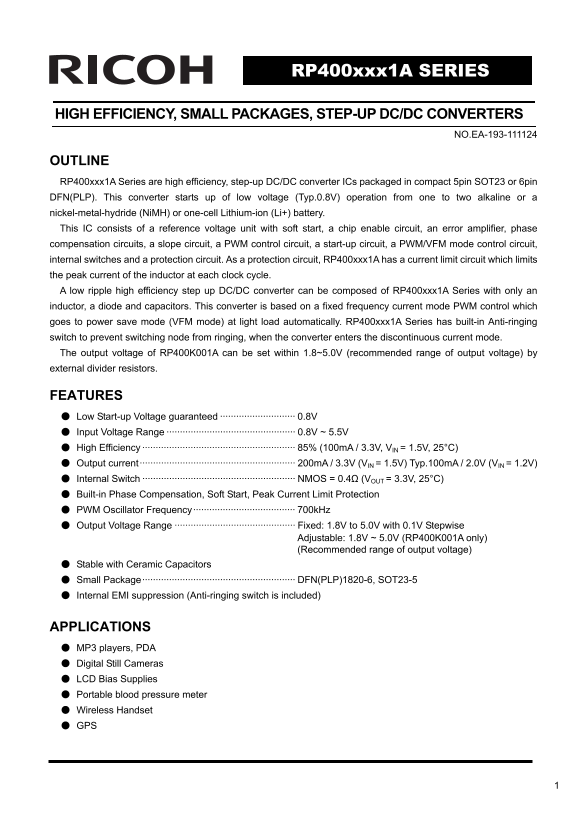
Page 1 Text Content
RP400xxx1A SERIES
HIGH EFFICIENCY, SMALL PACKAGES, STEP-UP DC/DC CONVERTERS
NO.EA-193-111124
OUTLINE RP400xxx1A Series are high efficiency, step-up DC/DC converter ICs packaged in compact 5pin SOT23 or 6pin DFN(PLP). This converter starts up of low voltage (Typ.0.8V) operation from one to two alkaline or a nickel-metal-hydride (Ni MH) or one-cell Lithium-ion (Li+) battery. This IC consists of a reference voltage unit with soft start, a chip enable circuit, an error amplifier, phase compensation circuits, a slope circuit, a PWM control circuit, a start-up circuit, a PWM/VFM mode control circuit, internal switches and a protection circuit. As a protection circuit, RP400xxx1A has a current limit circuit which limits the peak current of the inductor at each clock cycle. A low ripple high efficiency step up DC/DC converter can be composed of RP400xxx1A Series with only an inductor, a diode and capacitors. This converter is based on a fixed frequency current mode PWM control which goes to power save mode (VFM mode) at light load automatically. RP400xxx1A Series has built-in Anti-ringing switch to prevent switching node from ringing, when the converter enters the discontinuous current mode. The output voltage of RP400K001A can be set within 1.8~5.0V (recommended range of output voltage) by external divider resistors.
FEATURES ● Low Start-up Voltage guaranteed ···························· 0.8V ● Input Voltage Range ················································ 0.8V ~ 5.5V ● High Efficiency ························································· 85% (100m A / 3.3V, VIN = 1.5V, 25°C) ● Output current·························································· 200m A / 3.3V (VIN = 1.5V) Typ.100m A / 2.0V (VIN = 1.2V) ● Internal Switch ························································· NMOS = 0.4Ω (VOUT = 3.3V, 25°C) ● Built-in Phase Compensation, Soft Start, Peak Current Limit Protection ● PWM Oscillator Frequency······································ 700k Hz ● Output Voltage Range ············································· Fixed: 1.8V to 5.0V with 0.1V Stepwise Adjustable: 1.8V ~ 5.0V (RP400K001A only) (Recommended range of output voltage) ● Stable with Ceramic Capacitors ● Small Package························································· DFN(PLP)1820-6, SOT23-5 ● Internal EMI suppression (Anti-ringing switch is included)
APPLICATIONS ● MP3 players, PDA ● Digital Still Cameras ● LCD Bias Supplies ● Portable blood pressure meter ● Wireless Handset ● GPS
Page Summary Contents For RICOH RP400xxx1A SERIES HIGH-EFFICIENCY, SMALL-PACKAGE, STEP-UP DC-DC CONVERTERS
Manual Details
| Brand | Ricoh |
|---|---|
| Pages | 16 |
| File Size | 472.73 KB |
| Published | June 01, 2026 |
Enter the captcha to get the download link:

Frequently Asked Questions
What external components are needed for this converter?
A full DC/DC converter requires the RP400xxx1A IC, an inductor, a diode, and capacitors.
How can I set the output voltage range?
The output voltage of configurable models (RP400K001A) can be set between 1.8V and 5.0V using external divider resistors.
What low-voltage scenarios are supported?
It features guaranteed low startup voltage (Typ. 0.8V), allowing operation from single or dual alkaline/NiMH batteries.
What built-in protection mechanisms does the IC possess?
Protection includes a current limit circuit, soft start functionality, and an anti-ringing switch to prevent switching node ringing.