Fairchild NZT660 NZT660A PNP Low Saturation Transistor Data Handbook
Summary
The NZT660/NZT660A is a high-performance PNP Low Saturation Transistor, designed for robust power switching applications requiring both high current gain and low saturation voltage up to 3A continuous. This datasheet provides comprehensive technical specifications necessary for electrical engineers and circuit designers. It details absolute maximum ratings, small signal parameters, efficiency curves, thermal characteristics, and operational limits, ensuring optimal integration into demanding power electronics systems.
Page 1 Text Content
ZT660/N ZT660A PN P Low Saturation Transistor
April 2005
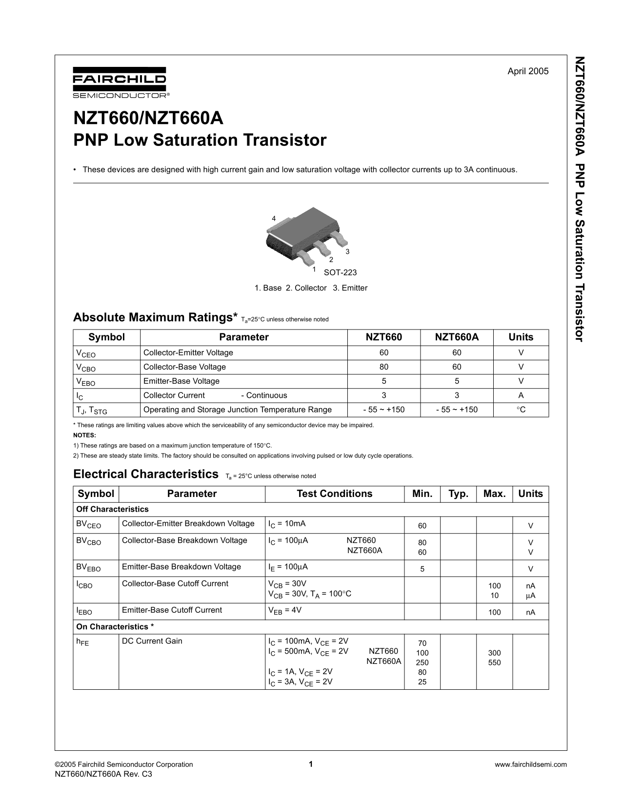
NZT660/NZT660A PNP Low Saturation Transistor These devices are designed with high current gain and low saturation voltage with collector currents up to 3A continuous.
SOT-2231
1. Base 2. Collector 3. Emitter
Absolute Maximum Ratings* Ta=25°C unless otherwise noted Symbol Parameter NZT660 NZT660A Units VCEO Collector-Emitter Voltage VCBO Collector-Base Voltage
VEBO Emitter-Base Voltage
IC Collector Current - Continuous
TJ, TSTG Operating and Storage Junction Temperature Range - 55 ~ +150 - 55 ~ +150 °C
* These ratings are limiting values above which the serviceability of any semiconductor device may be impaired. NOTES:
1) These ratings are based on a maximum junction temperature of 150°C. 2) These are steady state limits. The factory should be consulted on applications involving pulsed or low duty cycle operations.
Electrical Characteristics Ta = 25°C unless otherwise noted Symbol Parameter Test Conditions Min. Typ. Max. Units Off Characteristics BVCEO Collector-Emitter Breakdown Voltage IC = 10m A BVCBO Collector-Base Breakdown Voltage IC = 100µA NZT660
NZT660A
BVEBO Emitter-Base Breakdown Voltage IE = 100µA
ICBO Collector-Base Cutoff Current VCB = 30V
VCB = 30V, TA = 100°C µA
IEBO Emitter-Base Cutoff Current VEB = 4V
On Characteristics *
h FE DC Current Gain IC = 100m A, VCE = 2V
IC = 500m A, VCE = 2V NZT660 NZT660A IC = 1A, VCE = 2V IC = 3A, VCE = 2V
©2005 Fairchild Semiconductor Corporation www.fairchildsemi.com NZT660/NZT660A Rev. C3
Page Summary Contents For Fairchild NZT660 NZT660A PNP Low Saturation Transistor Data Handbook
Manual Details
| Brand | Fairchild |
|---|---|
| Pages | 5 |
| File Size | 429.60 KB |
| Published | July 06, 2026 |
Enter the captcha to get the download link:

Frequently Asked Questions
What is the maximum continuous collector current for this transistor?
The device supports a continuous collector current of up to 3A.
Are there limits on the operating temperature range?
Yes, the junction temperature range for operation and storage is -55 to +150 °C.
Is this component suitable for use in life support systems?
No, Fairchild requires explicit written approval before using these products as critical components in life support devices or systems.