Fairchild BCV26 PNP Darlington Transistor Data Sheet / User Manual
Summary
This high-performance PNP Darlington Transistor, packaged in SOT-23, is engineered for reliable power switching and amplification in demanding electronic circuits that require extremely high current gain up to 800 mA. The manual provides comprehensive technical data, including absolute maximum ratings, detailed small signal electrical characteristics, thermal dissipation limits, and saturation curves. It serves as a crucial resource for electronics engineers designing circuits needing precise and reliable power handling capacity.
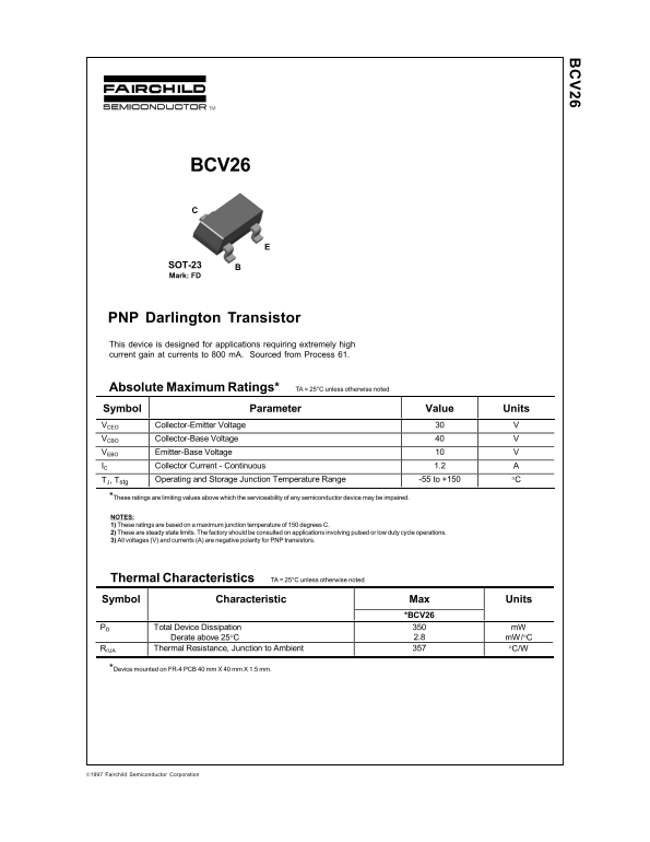
Page 1 Text Content
BCV26
SOT-23 Mark: FD
PNP Darlington Transistor This device is designed for applications requiring extremely high current gain at currents to 800 m A. Sourced from Process 61.
Absolute Maximum Ratings* TA = 25°C unless otherwise noted Symbol Parameter Value Units VCEO Collector-Emitter Voltage VCBO Collector-Base Voltage VEBO Emitter-Base Voltage IC Collector Current - Continuous 1.2
TJ, Tstg Operating and Storage Junction Temperature Range -55 to +150 °C
*These ratings are limiting values above which the serviceability of any semiconductor device may be impaired. NOTES: 1) These ratings are based on a maximum junction temperature of 150 degrees C. 2) These are steady state limits. The factory should be consulted on applications involving pulsed or low duty cycle operations. 3) All voltages (V) and currents (A) are negative polarity for PNP transistors.
Thermal Characteristics TA = 25°C unless otherwise noted Symbol Characteristic Max Units
*BCV26
PD Total Device Dissipation m W
Derate above 25°C 2.8 m W/°C
RθJA Thermal Resistance, Junction to Ambient °C/W
*Device mounted on FR-4 PCB 40 mm X 40 mm X 1.5 mm.
1997 Fairchild Semiconductor Corporation
Page Summary Contents For Fairchild BCV26 PNP Darlington Transistor Data Sheet / User Manual
Manual Details
| Brand | Fairchild |
|---|---|
| Pages | 7 |
| File Size | 215.10 KB |
| Published | June 16, 2026 |
Enter the captcha to get the download link:

Frequently Asked Questions
What's the maximum current this transistor can handle?
Continuous collector current is 1.2A.
How is the transistor packaged for delivery?
Shipped in tape on 7" (3000 units) or 13" reels (10000 units).
Is this transistor suitable for medical implants?
Not authorized for life support devices without Fairchild's written approval.
What's the typical current gain at 100mA?
Typical pulsed gain is 20,000 at 100mA/VCE=5V.
What power dissipation is allowed at 25°C?
Max power dissipation is 350mW at 25°C.