Fairchild NZT753 PNP Current Driver Transistor Data Sheet
Summary
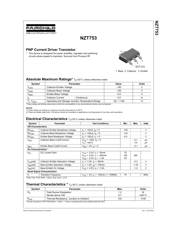
The NZT753 is a high-performance PNP current driver transistor engineered specifically for power amplifier, regulator, and rapid switching circuits where speed and reliability are essential. This comprehensive datasheet provides detailed technical specifications including absolute maximum ratings, low-dropout saturation voltages, high DC current gain, and transient frequency data (fT). It is the ideal solution for electronics designers who require robust performance in demanding, high-speed power applications.
Page 1 Text Content
ZT753
NZT753
PNP Current Driver Transistor This device is designed for power amplifier, regulator and switching circuits where speed is important. Sourced from Process 5P.
SOT-2231
1. Base 2. Collector 3. Emitter
Absolute Maximum Ratings* TA=25°C unless otherwise noted Symbol Parameter Value Units VCEO Collector-Emitter Voltage - 100
VCBO Collector-Base Voltage - 120
VEBO Emitter-Base Voltage - 5.0
IC Collector Current - Continuous - 4.0 TJ, TSTG Operating and Storage Junction Temperature Range - 55 ~ +150 °C
*These ratings are limiting values above which the serviceability of any semiconductor device may be impaired.
NOTES: 1) These ratings are based on a maximum junction temperature of 150°C. 2) These are steady state limits. The factory should be consulted on applications involving pulsed or low duty cycle operations.
Electrical Characteristics TA=25°C unless otherwise noted Symbol Parameter Test Conditions Min. Max. Units Off Characteristics
BVCEO Collector-Emitter Breakdown Voltage IC = -10m A, IB = 0 -100 BVCBO Collector-Base Breakdown Voltage IC = -100µA, IE = 0 -120 BVEBO Emitter-Base Breakdown Voltage IE = -100µA, IC = 0 -5.0 ICBO Collector-Base Cutoff Current VCB = -100V, IE = 0 -0.1 µA
TA = 100°C -10 µA
IEBO Emitter-Base Cutoff Current VEB = -4V, IC = 0 -0.1 µA
On Characteristics *
h FE DC Current Gain VCE = -2.0V, IC = -50m A
VCE = -2.0V, IC = -500m A VCE = -2.0V, IC = -1.0A
VCE(sat) Collector-Emitter Saturation Voltage IC = -1.0A, IC = -50m A -0.3 VBE(sat) Base-Emitter Saturation Voltage IC = -1.0A, IB = -100m A -1.25 VBE(on) Base-Emitter On Voltage VCE = -2.0V, IC = -1.0A, -1.0
Small Signal Characteristics
f T Transition Frequency VCE = -5V, IC = -100m A, f = 100MHz MHz
*Pulse Test: Pulse Width ≤ 300µs, Duty Cycle ≤ 2.0%
Thermal Characteristics * TA=25°C unless otherwise noted Symbol Parameter Max. Units
PD Total Device Dissipation 1.2 Derate above 25C 9.7 m W/°C RθJA Thermal Resistance, Junction to Ambient °C/W
* Device mounted on FR-4 PCB 36mm × 18mm × 1.5mm; mounting pad for the collector lead min 6cm2.
©2003 Fairchild Semiconductor Corporation Rev. A, April 2003
Page Summary Contents For Fairchild NZT753 PNP Current Driver Transistor Data Sheet
Manual Details
| Brand | Fairchild |
|---|---|
| Pages | 3 |
| File Size | 39.17 KB |
| Published | June 02, 2026 |
Enter the captcha to get the download link:

Frequently Asked Questions
What types of circuits is this transistor designed for?
It is designed for power amplifier, regulator and switching circuits where speed is important.
What are the absolute maximum operating temperatures?
The operating junction temperature range is -55 to +150 °C.
What is the continuous collector current rating?
The continuous Collector Current (I_C) is 4.0 A.
How do I calculate device derating above 25°C?
The power dissipation at higher temperatures must be derated at a rate of 9.7 mW/°C.