FAIRCHILD 2N5771 MMBT5771 PNP Switching Transistor Data Manual
Summary
This comprehensive datasheet provides technical specifications for a highly reliable PNP Switching Transistor. It is designed for engineers needing components capable of high-speed saturated switching at collector currents up to 100 mA. The manual details key electrical parameters, including absolute maximum ratings, breakdown voltages (CEO/CBO), thermal dissipation curves, and detailed small-signal characteristics. This resource is essential for circuit designers selecting a robust power switch component built for precision electronics applications.
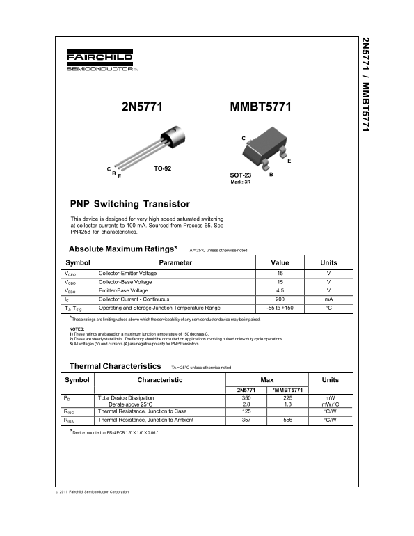
Page 1 Text Content
2N5771 MMBT5771
TO-92
SOT-23 Mark: 3R
PNP Switching Transistor This device is designed for very high speed saturated switching at collector currents to 100 m A. Sourced from Process 65. See PN4258 for characteristics.
Absolute Maximum Ratings* TA = 25°C unless otherwise noted Symbol Parameter Value Units VCEO Collector-Emitter Voltage VCBO Collector-Base Voltage VEBO Emitter-Base Voltage 4.5 IC Collector Current - Continuous m A
TJ, Tstg Operating and Storage Junction Temperature Range -55 to +150 °C
*These ratings are limiting values above which the serviceability of any semiconductor device may be impaired. NOTES: 1) These ratings are based on a maximum junction temperature of 150 degrees C. 2) These are steady state limits. The factory should be consulted on applications involving pulsed or low duty cycle operations. 3) All voltages (V) and currents (A) are negative polarity for PNP transistors.
Thermal Characteristics TA = 25°C unless otherwise noted Symbol Characteristic Max Units
2N5771 *MMBT5771
PD Total Device Dissipation m W
Derate above 25°C 2.8 1.8 m W/°C
RθJC Thermal Resistance, Junction to Case °C/W RθJA Thermal Resistance, Junction to Ambient °C/W
*Device mounted on FR-4 PCB 1.6" X 1.6" X 0.06."
2011 Fairchild Semiconductor Corporation
Page Summary Contents For FAIRCHILD 2N5771 MMBT5771 PNP Switching Transistor Data Manual
Manual Details
| Brand | Fairchild |
|---|---|
| Pages | 10 |
| File Size | 585.40 KB |
| Published | May 31, 2026 |
Enter the captcha to get the download link:

Frequently Asked Questions
What is the maximum continuous collector current rating?
The device has a nominal continuous collector current ($I_C$) of 200 mA.
Is this transistor suitable for life support systems?
No, its use as a critical component in life support devices requires express written approval from Fairchild Semiconductor Corporation.
How do I account for temperature changes when calculating power dissipation?
Above 25°C, the total device dissipation must be derated based on the rate of 2.8 mW/°C.
Can these absolute ratings be used if I operate it cyclically (pulsed operation)?
Engineers should consult the factory for applications involving pulsed or low duty cycle operations.