Delta HMI HMC07-N500H52 Installation Manual
Summary
This comprehensive manual serves as a detailed guide for the installation, wiring, and operation of the Delta HMC Series Human Machine Interface (HMI). It provides essential safety precautions, connection diagrams for various industrial interfaces (including RS-422 and DMCNet), and setup instructions for professional technicians and system integrators. Designed for general-purpose applications, this resource ensures correct setup, maintenance, and optimal performance of the 7-inch TFT LCD controller within demanding industrial environments.
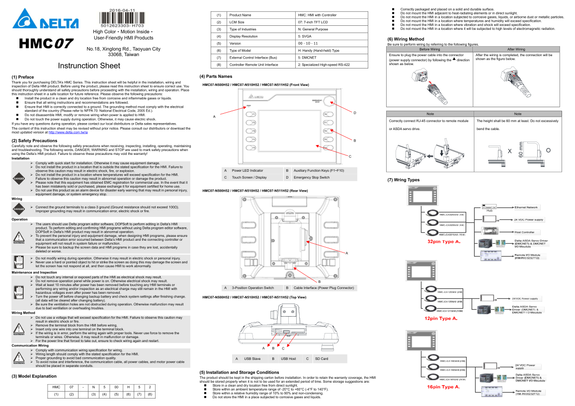
Page 1 Text Content
Correctly packaged and placed on a solid and durable surface. Do not mount the HMI adjacent to heat-radiating elements or in direct sunlight.
(1) Product Name HMC: HMI with Controller
Do not mount the HMI in a location subjected to corrosive gases, liquids, or airborne dust or metallic particles. Do not mount the HMI in a location where temperatures and humidity will exceed specification.
(2) LCM Size 07: 7-inch TFT LCD
Do not mount the HMI in a location where vibration and shock will exceed specification. (3) Type of Industries N: General Purpose Do not mount the HMI in a location where it will be subjected to high levels of electromagnetic radiation.
High Color‧Motion Inside‧
(4) Display Resolution 5: SVGA
User-Friendly HMI Products
(6) Wiring Method
(5) Version 00、10、11 Be sure to perform wiring by referring to the following figures.
HMC07
No.18, Xinglong Rd., Taoyuan City Before Wiring After Wiring
(6) Type of Model H: Handy (Hand-held) Type
33068, Taiwan Ensure to plug the power cable into the connector After the wiring is completed, the connection will be
(7) External Control Interface (Bus) 5: DMCNET
shown as the figure below.
(power supply connector) by following the direction (8) Controller Remote Unit Interface 2: Specialized High-speed RS-422 shown as below.
Instrunction Sheet
(1) Preface (4) Parts Names
Thank you for purchasing DELTA’s HMC Series. This instruction sheet will be helpful in the installation, wiring and
HMC07-N500H52 / HMC07-N510H52 / HMC07-N511H52 (Front View)
inspection of Delta HMI product. Before using the product, please read this instruction sheet to ensure correct use. You should thoroughly understand all safety precautions before proceeding with the installation, wiring and operation. Place this instruction sheet in a safe location for future reference. Please observe the following precautions: Install the product in a clean and dry location free from corrosive and inflammable gases or liquids. Ensure that all wiring instructions and recommendations are followed. Ensure that HMI is correctly connected to a ground. The grounding method must comply with the electrical standard of the country (Please refer to NFPA 70: National Electrical Code, 2005 Ed.).
Note Note
Do not disassemble HMI, modify or remove wiring when power is applied to HMI. Do not touch the power supply during operation. Otherwise, it may cause electric shock.
Correctly connect RJ-45 connector to remote module The height shall be 60 mm at least. Do not excessively
If you have any questions during operation, please contact our local distributors or Delta sales representatives. The content of this instruction sheet may be revised without prior notice. Please consult our distributors or download the or ASDA servo drive. bend the cable. most updated version at http://www.delta.com.tw/ia
(2) Safety Precautions Carefully note and observe the following safety precautions when receiving, inspecting, installing, operating, maintaining and troubleshooting. The following words, DANGER, WARNING and STOP are used to mark safety precautions when using the Delta’s HMI product. Failure to observe these precautions may void the warranty! Installation
Comply with quick start for installation. Otherwise it may cause equipment damage. Do not install the product in a location that is outside the stated specification for the HMI. Failure to
observe this caution may result in electric shock, fire, or explosion. A Power LED Indicator B Auxiliary Function Keys (F1~F10)
Do not install the product in a location where temperatures will exceed specification for the HMI.
C Touch Screen / Display D Emergency Stop Switch
Failure to observe this caution may result in abnormal operation or damage the product.
(7) Wring Types
Please note that this equipment has obtained EMC registration for commercial use. In the event that it has been mistakenly sold or purchased, please exchange it for equipment certified for home use. Do not use this product as an alarm device for disaster early warning that may result in personal injury, HMC07-N500H52 / HMC07-N510H52 / HMC07-N511H52 (Rear View) equipment damage, or system emergency stop.
Wiring
Connect the ground terminals to a class-3 ground (Ground resistance should not exceed 100Ω). Improper grounding may result in communication error, electric shock or fire.
Operation
The users should use Delta program editor software, DOPSoft to perform editing in Delta's HMI product. To perform editing and confirming HMI programs without using Delta program editor software, DOPSoft in Delta's HMI product may result in abnormal operation. To prevent the personal injury and equipment damage, when designing HMI programs, please ensure that a communication error occurred between Delta’s HMI product and the connecting controller or equipment will not result in system failure or malfunction. Please be sure to backup the screen data and HMI programs in case they are lost, accidentally deleted or worse.
Do not modify wiring during operation. Otherwise it may result in electric shock or personal injury. Never use a hard or pointed object to hit or strike the screen as doing this may damage the screen and let the screen has not respond at all, and then cause HMI to work abnormally.
Maintenance and Inspection
Do not touch any internal or exposed parts of the HMI as electrical shock may result. Do not remove operation panel while power is on. Otherwise electrical shock may result. Wait at least 10 minutes after power has been removed before touching any HMI terminals or
performing any wiring and/or inspection as an electrical charge may still remain in the HMI with A 3-Position Operation Switch B Cable Interface (Power Plug Connector)
hazardous voltages even after power has been removed. Turn the power off before changing backup battery and check system settings after finishing change. HMC07-N500H52 / HMC07-N510H52 / HMC07-N511H52 (Top View) (all data will be cleared after changing battery). Be sure the ventilation holes are not obstructed during operation. Otherwise malfunction may result due to bad ventilation or overheating troubles.
Wiring Method
Do not use a voltage that will exceed specification for the HMI. Failure to observe this caution may result in electric shock or fire. Remove the terminal block from the HMI before wiring. Insert only one wire into one terminal on the terminal block. If the wiring is in error, perform the wiring again with proper tools. Never use force to remove the terminals or wires. Otherwise, it may result in malfunction or damage. For the power line that forced to take out, ensure to check wiring again and restart.
Communication Wiring
Comply with communication wiring specification for wiring. Wiring length should comply with the stated specification for the HMI. Proper grounding to avoid bad communication quality. USB Slave B USB Host C SD Card To avoid noise and interference, the communication cable, all power cables, and motor power cable should be placed in separate conduits.
(5) Installation and Storage Conditions
(3) Model Explanation
The product should be kept in the shipping carton before installation. In order to retain the warranty coverage, the HMI should be stored properly when it is not to be used for an extended period of time. Some storage suggestions are: Store in a clean and dry location free from direct sunlight.
HMC 07 - N 5 00 H 5 2
Store within an ambient temperature range of -20°C to +60°C (-4°F to 140°F). Store within a relative humidity range of 10% to 90% and non-condensing.
Do not store the HMI in a place subjected to corrosive gases and liquids.
Page Summary Contents For Delta HMI HMC07-N500H52 Installation Manual
Manual Details
| Brand | Delta |
|---|---|
| Pages | 8 |
| File Size | 1.62 MB |
| Published | June 06, 2026 |
Enter the captcha to get the download link:

Frequently Asked Questions
What are the recommended working environments for the HMI?
Install the product in a clean, dry location, free from corrosive/inflammable gases or liquids. Avoid direct sunlight, heat-radiating elements, dust, metallic particles, and excessive vibration/shock.
How should I ground the HMI unit?
The ground terminals must be connected to a class-3 ground, ensuring the resistance does not exceed 100Ω. Improper grounding can cause electric shock or fire.
What software is required for editing HMI programs?
Users should use Delta program editor software (DOPSoft) to perform editing and confirming HMI programs in this product.
Are there limitations on the displayed resolution and size?
The display features a 7-inch TFT LCD with an SVGA resolution of 800 x 600 pixels. The overall dimensions are 238 x 199 x 129 mm.
What is the recommended power supply capacity?
The suggested power supply unit capacity should be 1.5 to 2 times the marked consumption power (excluding external peripherals) to ensure proper operation.