User's Guide and Manual for RICOH R1204x Series
Summary
This CMOS-based PWM/VFM step-up DC/DC converter is engineered to provide efficient, high-precision power for driving white LEDs and PMOLEDs in demanding applications like handheld equipment. The R1204x series offers advanced protection circuits including UVLO, OVP, and thermal shutdown, ensuring reliable performance. This manual provides comprehensive technical documentation covering two versions (A/D and B/C/E/F), detailed selection guides for optimal current control, and application diagrams to assist electrical engineers in seamless integration into next-generation LED lighting systems.
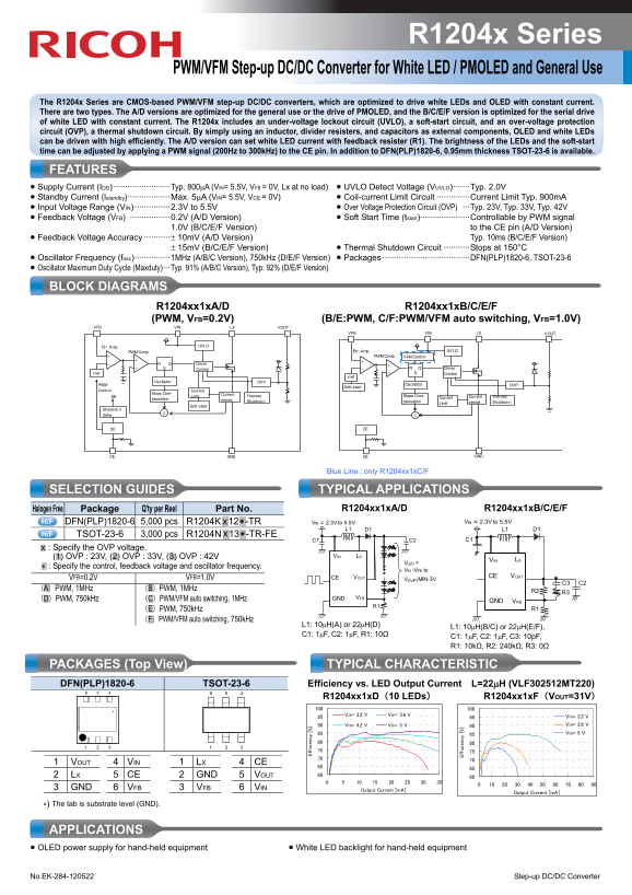
Page 1 Text Content
R1204x Series
PWM/VFM Step-up DC/DC Converter for White LED / PMOLED and General Use
The R1204x Series are CMOS-based PWM/VFM step-up DC/DC converters, which are optimized to drive white LEDs and OLED with constant current. There are two types. The A/D versions are optimized for the general use or the drive of PMOLED, and the B/C/E/F version is optimized for the serial drive of white LED with constant current. The R1204x includes an under-voltage lockout circuit (UVLO), a soft-start circuit, and an over-voltage protection circuit (OVP), a thermal shutdown circuit. By simply using an inductor, divider resisters, and capacitors as external components, OLED and white LEDs can be driven with high efficiently. The A/D version can set white LED current with feedback resister (R1). The brightness of the LEDs and the soft-start time can be adjusted by applying a PWM signal (200Hz to 300k Hz) to the CE pin. In addition to DFN(PLP)1820-6, 0.95mm thickness TSOT-23-6 is available.
FEATURES • Supply Current (IDD) ························Typ. 800μA (VIN= 5.5V, VFB = 0V, Lx at no load) • UVLO Detect Voltage (VUVLO)·······Typ. 2.0V • Standby Current (Istandby)··················Max. 5μA (VIN= 5.5V, VCE = 0V) • Coil-current Limit Circuit ··············Current Limit Typ. 900m A • Input Voltage Range (VIN) ···············2.3V to 5.5V • Over Voltage Protection Circuit (OVP) ···Typ. 23V, Typ. 33V, Typ. 42V • Feedback Voltage (VFB) ·················0.2V (A/D Version) • Soft Start Time (tstart)·····················Controllable by PWM signal
1.0V (B/C/E/F Version) to the CE pin (A/D Version)
• Feedback Voltage Accuracy ···········± 10m V (A/D Version) Typ. 10ms (B/C/E/F Version)
± 15m V (B/C/E/F Version) • Thermal Shutdown Circuit ···········Stops at 150°C
• Oscillator Frequency (fosc)···············1MHz (A/B/C Version), 750k Hz (D/E/F Version) • Packages ·····································DFN(PLP)1820-6, TSOT-23-6 • Oscillator Maximum Duty Cycle (Maxduty)···Typ. 91% (A/B/C Version), Typ. 92% (D/E/F Version)
BLOCK DIAGRAMS R1204xx1x A/D R1204xx1x B/C/E/F
ff ic ie cy
(PWM, VFB=0.2V) (B/E:PWM, C/F:PWM/VFM auto switching, VFB=1.0V)
VFB VIN LX VOUT
VFB VIN LX VOUT
Err. Amp. UVLO
PWM Comp. Err. Amp. UVLO
PWM Comp. VFM Control
Driver
Control S Driver
vref Control S
Oscillator OVP
PWM Oscillator OVPSoft-start
Control Current
Slope Com- Current
EN Limit Thermal Slope Com- Current Current Thermal
pensation sense
Shutdow pensation Limit sense Shutdow
Soft-start
Shutdow delay
CE CE
GNDCE GNDCE
ff ic ie nc
Blue Line : only R1204xx1x C/F
SELECTION GUIDES TYPICAL APPLICATIONS
Halogen Free Package Q'ty per Reel Part No. R1204xx1x A/D R1204xx1x B/C/E/F
DFN(PLP)1820-6 5,000 pcs R1204K .x.12.∗ -TR VIN = 2.3V to 5.5V VIN = 2.3V to 5.5V
TSOT-23-6 3,000 pcs R1204N .x.13.∗ -TR-FE
.x. : Specify the OVP voltage.
(1) OVP : 23V, (2) OVP : 33V, (3) OVP : 42V VIN LX
VIN LX
VLED =
.∗ : Specify the control, feedback voltage and oscillator frequency.
VIN -VFB to
VFB=0.2V VFB=1.0V CE VOUT CE VOUT
VOVP1MIN-3V
(A)PWM, 1MHz (B)PWM, 1MHz R2
(D)PWM, 750k Hz (C)PWM/VFM auto switching, 1MHz GND VFB
GND VFB
(E)PWM, 750k Hz R1
(F)PWM/VFM auto switching, 750k Hz
L1: 10μH(A) or 22μH(D)
L1: 10μH(B/C) or 22μH(E/F),
PACKAGES (Top View) TYPICAL CHARACTERISTIC DFN(PLP)1820-6 TSOT-23-6 Efficiency vs. LED Output Current L=22μH (VLF302512MT220) 6 5 4 6 5 4
R1204xx1x D(10 LEDs) R1204xx1x F(VOUT=31V)
Vin= 3.2 V Vin= 3.6 V Vin= 3.2 V
Vin= 4.2 V Vin= 5 V Vin= 3.6 V Vin= 5 V
1 VOUT 4 VIN 1 LX 4 CE 2 LX 5 CE 2 GND 5 VOUT 3 GND 6 VFB 3 VFB 6 VIN Output Current [m A]
Output Current [m A]
∗) The tab is substrate level (GND).
APPLICATIONS • OLED power supply for hand-held equipment • White LED backlight for hand-held equipment
No.EK-284-120522 Step-up DC/DC Converter
Page Summary Contents For User's Guide and Manual for RICOH R1204x Series
Manual Details
| Brand | Ricoh |
|---|---|
| Pages | 2 |
| File Size | 349.47 KB |
| Published | June 02, 2026 |
Enter the captcha to get the download link:

Frequently Asked Questions
What types are optimized for white LEDs versus PMOLED general use?
A/D versions are optimized for general use or PMOLED, while B/C/E/F versions are optimized for serial drive of white LED with constant current.
How is the LED brightness adjusted using the PWM signal?
The brightness can be controlled by applying a PWM signal (200Hz to 300kHz) to the CE pin. The soft-start time is set to Typ. 10ms within the IC when controlling the LED.
What advanced protection features does the R1204x series include?
It includes under-voltage lockout (UVLO), over-voltage protection (OVP), thermal shutdown, and a soft-start circuit.
What is the recommended frequency range for PWM signaling to avoid audible noise?
The user should use the PWM signal in the high frequency area, suggesting avoiding 20kHz or less to prevent audible sounds.