# A B C D E F G H I J K L M N O P Q R S T U V W X Y Z

RICOH R5540K series Owner's Manual and User Guide

Summary

This advanced N-channel Load Switch IC is engineered for highly efficient secondary power management in portable electrical devices, such as mobile communications equipment and cameras. Featuring ultra-low supply current, built-in soft-start, and over-current protection, it safely switches power from DC/DC outputs. This manual provides comprehensive technical specifications, selection guides (for varied output currents), and pin configurations for system designers implementing reliable, compact power circuits.
📄 Preview PAGE OF 15

Page 1 Text Content

R5540K SERIES

N-channel Load Switch IC

NO. EA-268-111028

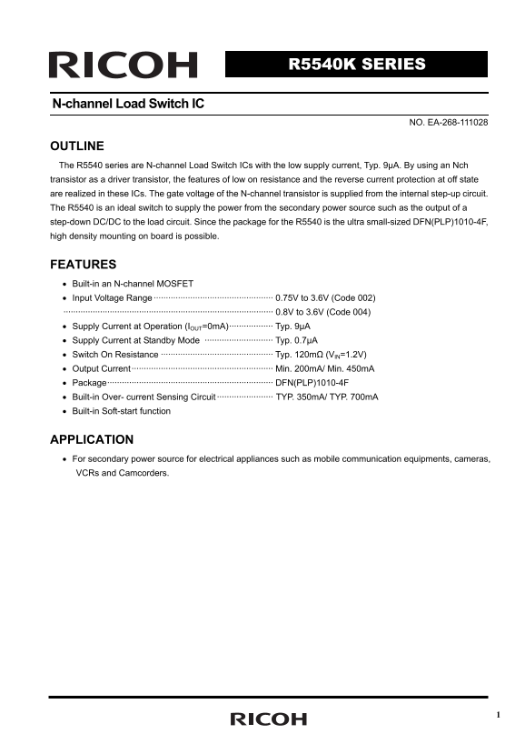
OUTLINE The R5540 series are N-channel Load Switch ICs with the low supply current, Typ. 9µA. By using an Nch transistor as a driver transistor, the features of low on resistance and the reverse current protection at off state are realized in these ICs. The gate voltage of the N-channel transistor is supplied from the internal step-up circuit. The R5540 is an ideal switch to supply the power from the secondary power source such as the output of a step-down DC/DC to the load circuit. Since the package for the R5540 is the ultra small-sized DFN(PLP)1010-4F, high density mounting on board is possible.

FEATURES • Built-in an N-channel MOSFET • Input Voltage Range ················································· 0.75V to 3.6V (Code 002) ······················································································ 0.8V to 3.6V (Code 004) • Supply Current at Operation (IOUT=0m A)·················· Typ. 9µA • Supply Current at Standby Mode ···························· Typ. 0.7µA • Switch On Resistance ·············································· Typ. 120mΩ (VIN=1.2V) • Output Current·························································· Min. 200m A/ Min. 450m A • Package···································································· DFN(PLP)1010-4F • Built-in Over- current Sensing Circuit ······················· TYP. 350m A/ TYP. 700m A • Built-in Soft-start function

APPLICATION • For secondary power source for electrical appliances such as mobile communication equipments, cameras, VCRs and Camcorders.

Page Summary Contents For RICOH R5540K series Owner's Manual and User Guide

Page 1 R5540K SERIES N-channel Load Switch IC NO. EA-268-111028 OUTLINE The R5540 series are N-channel Load Switch ICs with the low supply current, Typ. 9µA. By using an Nch transistor as a driver transistor...
Page 2 BLOCK DIAGRAMS R5540Kxxx B R5540Kxxx C VIN VOUT VIN VOUT Soft Start Soft Start Gate Current Gate Current Control Limit Control Limit GNDCE GNDCE R5540Kxxx D Soft Start Gate Current Control Limit GNDCE
Page 3 SELECTION GUIDE The output current value, the auto-discharge function and the polarity of CE pin from "L" active, "H" active are selectable at the user’s request. Product Name Pack...
Page 4 PIN DESCRIPTION ● R5540K:DFN(PLP)1010-4F Symbol Pin Description Pin No 1 GND Ground Pin CE / CE 2 Chip Enable Pin (“L” Active / “H” Active) 3 V Input Pin IN 4 V Output Pin OUT ABSOLUTE MAXIMUM RATINGS...
Page 5 ELECTRICAL CHARACTERISTICS = 0.75 to 3.6V(Code 002) , 0.8 to 3.6V(Code 004), CIN IN = 1μF, C = None, unless otherwise noted. OUT The specification in surrounded by is guaranteed by design at all tempe...
Page 6 TYPICAL APPLICATION V BATT DC/DC Load VIN VOUT Converter C IN =1µF R5540K GNDCE COUT R L Enable Signal Basically, the R5540K series do not require a bypass capacitor between VIN and GND, however, cons...
Page 7 TYPICAL CHARACTERISTIC 1) Output Voltage vs. Output Current C =1u F, C OUT =1u F IN VIN=1.8[V] VIN=1.8[V] VIN=1.2[V] VIN=1.2[V] VIN=0.8[V] VIN=0.8[V] IOUT [A] IOUT[A] =1. 2V, CIN IN =1u F, Topt=25°C) ...
Page 8 VCE VCE (1V/div) (1V/div) VOUT VOUT (0.2V/div) (0.2V/div) IOUT IOUT (20m A/div) RL=10[Ω] (10m A/div) RL=500[Ω] COUT=1[μF] COUT=1[μF] TIME(100μs/div) TIME(50μs/div) VCE VCE (1V/div) (1V/div) VOUT VOUT ...
Page 9 IS TS [μ 3) Inrush current vs. output capacitor (002x) 4) Input voltage vs. Turn-on speed VCE Tr vs VIN tr vs VIN Topt=25[℃](1V/div) COUT =4.7[μF] COUT =10[μF] VOUT COUT =22[μF] (0.2V/div) RL=10Ω COUT...
Page 10 [m VC [V IS [m 9) CE Input voltage "H" vs. Temperature 10) CE Input voltage "H" vs. VDD CE Input Voltage "H" VCEH vs VIN Topt [°C] Input Voltage [V] 11) CE Input voltage ...
Page 11 R5540K tf [μ s] IR EV [μ tr [μ s] 17) Output Rise time vs. Temperature 18) Output Rise time vs. Input voltage Output Turn On Delay tr vs VIN VIN=0.8V VIN=1.8V VIN=3.6V -40°C 25°C 85°CCOUT =0.1[μF] COU...
Page 12 23) Discharge resistance vs. Temperature 24) Discharge resistance vs. Input voltage Discharge Resistance RLOW vs VIN VIN=0.8V VIN=1.2V VIN=3.6V Topt [℃] Input Voltage [V] 25) Current limit vs. Tempera...
Page 13 Turn-on/ turn-off waveform (V = 1.2[V]) IN VCE VCE (0.5V/div) (0.5V/div) t ON 124.6[μs] t ON 45.03[μs] tr 124.3[μs] tf 7.13[μs] VOUT VOUT (0.5V/div) (0.5V/div) No Load No Load TIME(50μs/div) TIME(10μs...
Page 14 ow er is si pa tio (m POWER DISSIPATION (DFN(PLP)1010-4F) This specification is at mounted on board. Power Dissipation (PD) depends on conditions of mounting on board. This specification is based on t...
Page 15 1. The products and the product specifications described in this document are subject to change or discontinuation of production without notice for reasons such as improvement. Therefore, before decid...

Manual Details

Brand Ricoh
Pages 15
File Size 542.57 KB
Published May 27, 2026
67 views

Enter the captcha to get the download link:

captcha

Frequently Asked Questions

What is the R5540K best used for?

It is ideal for supplying secondary power from step-down DC/DC sources to electrical appliances such as cameras or mobile communication equipment.

Do I need to worry about board space with this IC?

No, since its package is the ultra small DFN(PLP)1010-4F, high density mounting on a board is possible.

What protective functions are included in the R5540K?

It features a built-in over-current sensing circuit and an integrated soft-start function for stable operation.

How do I select different output current capabilities?

The output current value can be designated by codes: 002 provides 200mA, and 004 provides 450mA.