# A B C D E F G H I J K L M N O P Q R S T U V W X Y Z

RICOH R5524N series Owner's Manual and User Guide

Summary

The R5524N series is a compact, CMOS-based high-side MOSFET switch IC engineered for reliable USB power supply systems. Featuring built-in protection against over-current, thermal events, and undervoltage, it ensures stable power management across various demanding applications. This technical guide provides detailed specifications, selection guides, and application data crucial for engineers developing devices like PCs, Set Top Boxes, and digital peripherals.
📄 Preview PAGE OF 15

Page 1 Text Content

R5524N SERIES

USB HIGH-SIDE POWER SWITCH

NO.EA-188-111212

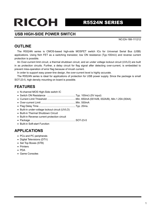
OUTLINE The R5524N series is CMOS-based high-side MOSFET switch ICs for Universal Serial Bus (USB) applications. Using Nch FET as a switching transistor, low ON resistance (Typ.100mΩ) and reverse current protection is possible. An Over-current limit circuit, a thermal shutdown circuit, and an under voltage lockout circuit (UVLO) are built in as protection circuits. Further, a delay circuit for flag signal after detecting over-current, is embedded to prevent miss-operation of error flag because of inrush current. In order to support easy power-line design, the over-current level is highly accurate. The R5524N series is ideal for applications of protection for USB power supply. Since the package is small SOT-23-5, high density mounting on board is possible.

FEATURES • N-channel MOS High-Side switch IC • Switch ON Resistance ........................................Typ. 100mΩ (5V input) • Current Limit Threshold ........................................Min. 650m A (001A/B, 002A/B), Min.1.25A (004A) • Over-current Limit .................................................Min. 550m A • Flag Delay Time ....................................................Typ. 20ms. • Built-in under-voltage lockout circuit (UVLO) • Built-in Thermal Shutdown Circuit • Built-in Reverse current protection circuit • Package ................................................................SOT-23-5 • Built-in Soft-start Function

APPLICATIONS • PCs and PC peripherals • Digital Televisions (DTV) • Set Top Boxes (STB) • Printers • PDA • Game Consoles

Page Summary Contents For RICOH R5524N series Owner's Manual and User Guide

Page 1 R5524N SERIES USB HIGH-SIDE POWER SWITCH NO.EA-188-111212 OUTLINE The R5524N series is CMOS-based high-side MOSFET switch ICs for Universal Serial Bus (USB) applications. Using Nch FET as a switching ...
Page 2 BLOCK DIAGRAM R5524Nxxx A VIN VOUT GATE CURRENT EN CONTROL LIMIT FLG DELAY THERMAL SHUTDOWN R5524Nxxx B VI VOU GATE CURRENT EN CONTROL LIMIT FLG DELAY THERMAL SHUTDOWN
Page 3 SELECTION GUIDE The over-current limit protection type,the Current Limit Threshold and the auto discharge function for the ICs can be selected at the user’s request. Product Name Package Quantity per ...
Page 4 ABSOLUTE MAXIMUM RATINGS Symbol Item Rating Unit VIN Input Voltage 6.0 V VEN Enable Pin Input Voltage −0.3 to 6.0 V VFLG Flag Voltage −0.3 to 6.0 V IFLG Flag Current 14 m A VOUT Output Voltage −0.3 to...
Page 5 ELECTRICAL CHARACTERISTICS • R5524N Topt=25°C Symbol Item Conditions Min. Typ. Max. Unit VIN Input Voltage 2.7 5.5 V IDD1 Supply Current (Active Mode) VOUT=OPEN,EN=”H”,VIN=5V 110 180 μA IDD2 Supply Cu...
Page 6 RECOMMENDED OPERATING CONDITIONS (ELECTRICAL CHARACTERISTICS) All of electronic equipment should be designed that the mounted semiconductor devices operate within the recommended operating conditions....
Page 7 The Over-Current Limitation Function R5524N001A/001B has the built-in latch-off type over-current limit circuit. When the over-current is detected, the protection circuit becomes active and the switch...
Page 8 TEST CIRCUIT VIN VOUT VIN VOUT Series Series EN FLG VIN EN FLG Supply Current Test Circuit Switch ON Resistance Test Circuit VIN VOUT VIN VOUT 0.1μF R5524N 0.1μF R5524N Series Series GND GND EN FLG EN...
Page 9 up pl ur re nt 1 ( μA ut pu t O im (μ s) itc es is ta nc R5524N TYPICAL CHARACTERISTICS 1) Supply Current vs. Temperature 2) Supply Current vs. Input Voltage Temperature Topt (°C) Input Voltage VIN (V...
Page 10 ur re nt im it Th re sh ol ur re nt im it Th re sh ol R5524N VL ol ta ge LO (V TH (m TH (m 7) UVLO Voltage vs. Temperature 8) Output Voltage vs. Input Voltage 2.0 2.30 UVLO Threshold Voltage 1.5 1.0 U...
Page 11 na bl in In pu t V ol ta ge R5524N ve r C ur re nt im it Fl ag el ay im FD (m s) EN / V EN 2 ( IM (m A) 13) Over Current Limit vs. Temperature 14) Over Current Limit vs. Input Voltage Temperature Topt...
Page 12 19) Over-Current Response with Ramped Load 20) Over-Current Response with Ramped Load VIN=5V VIN=5V EN=”L” (5V/div) (5V/div) IOUT IOUT (200m A/div) (200m A/div) Time (5ms/div) Time (5ms/div) 21)Over-C...
Page 13 23) Thermal Shutdown Operation 24) Output Voltage vs. Output Current VIN=5V (5V/div) (5V/div) 2.0 1.5 1.0 VIN=5V 0.5 (500m A/div) 0.2 0.4 0.6 0.8 Time (50ms/div) Outpur Current IOUT (A) 25) Output ON ...
Page 14 output is shorted when without a bypass capacitor, because of the high side inductance of VIN pin, the ringing may be generated and it might be a cause of an unstable operation. • Pull-up resistance v...
Page 15 1. The products and the product specifications described in this document are subject to change or discontinuation of production without notice for reasons such as improvement. Therefore, before decid...

Manual Details

Brand Ricoh
Pages 15
File Size 398.45 KB
Published June 04, 2026
45 views

Enter the captcha to get the download link:

captcha

Frequently Asked Questions

How do I select the correct over-current limit threshold for my design?

You must select the appropriate combination of protection type and Current Limit Threshold (e.g., 001A/B, 002A/B, or 004A) from the selection guide.