Toshiba TOSHIBA CMOS Integrated Circuit Silicon Monolithic TB6537P, TB6537F Data Manual
Summary
Revolutionize your motor control systems with this advanced 3-phase full-wave sensorless controller for Brushless DC Motors (BLDC). This highly versatile circuit precisely controls voltage via PWM signals and offers comprehensive features, including lead angle adjustment, overcurrent protection, and precise commutation management. Ideal for engineers and device manufacturers requiring robust, high-performance motor drives in diverse applications—from robotics to industrial machinery. The accompanying documentation provides detailed technical specifications, pin assignments, and operational instructions necessary for seamless integration into your next design project.
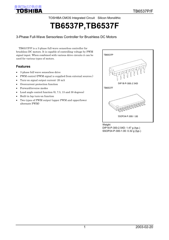
Page 1 Text Content
查询TB6537供应商
TB6537P/F
TOSHIBA CMOS Integrated Circuit Silicon Monolithic
TB6537P,TB6537F
3-Phase Full-Wave Sensorless Controller for Brushless DC Motors
TB6537P/F is a 3-phase full-wave sensorless controller for brushless DC motors. It is capable of controlling voltage by PWM
signal input. When combined with various drive circuits it can be TB6537P
used for various types of motors.
Features 3-phase full-wave sensorless drive PWM control (PWM signal is supplied from external sources.) Turn-on signal output current: 20 m A Overcurrent protection function
Forward/reverse modes TB6537F
Lead angle control function (0, 7.5, 15 and 30 degrees) Built-in lap turn-on function Two types of PWM output (upper PWM and upper/lower alternate PWM)
Weight DIP18-P-300-2.54D: 1.47 g (typ.) SSOP24-P-300-1.00: 0.32 g (typ.)
Page Summary Contents For Toshiba TOSHIBA CMOS Integrated Circuit Silicon Monolithic TB6537P, TB6537F Data Manual
Manual Details
| Brand | Toshiba |
|---|---|
| Pages | 15 |
| File Size | 136.97 KB |
| Published | June 05, 2026 |
Enter the captcha to get the download link:

Frequently Asked Questions
How can I adjust the lead angle setting?
Use input pins LA0 and LA1: Low, Low for 0 degrees; High, Low for 7.5 degrees; Low, High for 15 degrees; and High, High for 30 degrees.
What is required to disable PWM duty-100% signals?
A signal of High for 250 ns or longer is required to bypass the duty-100% input.
Are there any limitations regarding product use in critical applications?
The products are intended for general electronics applications and are not warranted for usage in equipment requiring extraordinarily high quality or reliability (e.g., medical instruments, aircraft systems).
What does SEL_OUT control?
SEL_OUT selects the synthesis method of the burn-in signal and PWM signal; Low enables Upper PWM, and High enables Upper/Lower alternate PWM.