# A B C D E F G H I J K L M N O P Q R S T U V W X Y Z

Toshiba CMOS Integrated Circuit Silicon Monolithic TB6548F Data Manual

Summary

The TB6548F is a specialized 3-phase full-wave PWM sensorless controller designed for efficient operation of brushless DC motors. This comprehensive manual provides engineers and designers with detailed technical specifications, pin assignments, and operational instructions for implementing advanced motor control systems. It covers features such as automatic sensorless drive modes, customizable lead angle setting (0° to 30°), direction control, and built-in overcurrent protection. Ideal for professionals developing various general electronics applications, including industrial automation and household appliances.
📄 Preview PAGE OF 13

Page 1 Text Content

TB6548F

TOSHIBA CMOS Integrated Circuit Silicon Monolithic

3-Phase Full-Wave PWM Sensorless Controller for Brushless DC Motors

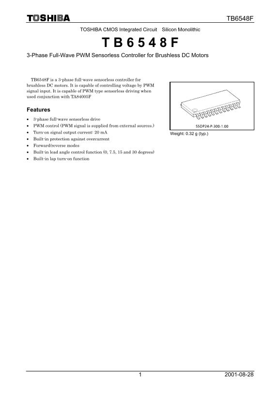
TB6548F is a 3-phase full-wave sensorless controller for brushless DC motors. It is capable of controlling voltage by PWM signal input. It is capable of PWM type sensorless driving when used conjunction with TA84005F

Features • 3-phase full-wave sensorless drive • PWM control (PWM signal is supplied from external sources.) • Turn-on signal output current: 20 m A

Weight: 0.32 g (typ.)

• Built-in protection against overcurrent • Forward/reverse modes • Built-in lead angle control function (0, 7.5, 15 and 30 degrees) • Built-in lap turn-on function

Page Summary Contents For Toshiba CMOS Integrated Circuit Silicon Monolithic TB6548F Data Manual

Page 1 TB6548F TOSHIBA CMOS Integrated Circuit Silicon Monolithic 3-Phase Full-Wave PWM Sensorless Controller for Brushless DC Motors TB6548F is a 3-phase full-wave sensorless controller for brushless DC mot...
Page 2 TB6548F Block Diagram VDD FG_OUT OUT_UP PWM PWM Control OUT_VP SEL_LAP OUT_WP Turn-on Signal Forming Circuit Rotation OUT_UN Timing CW_CCW Instruction Control Circuit OUT_VN OUT_WN Lead Angle Overcurr...
Page 3 TB6548F Pin Description Pin No. Symbol I/O Description Lead angle setting signal input pin 1 LA0 I • LA0 = Low, LA1 = Low: Lead angle 0 degree • LA0 = High, LA1 = Low: Lead angle 7.5 degree • LA0 = Lo...
Page 4 TB6548F Pin No. Symbol I/O Description W-phase upper turn-on signal output pin 21 OUT_WP O • W-phase winding wire positive ON/OFF switching pin • ON: Low, OFF: High W-phase lower turn-on signal output...
Page 5 TB6548F 4. PWM Control Upper turn-on signal (OUT-P) Lower turn-on signal (OUT-N) Output voltage of TA84005F
Page 6 TB6548F 5. Positional Variation Since positional detection is performed in synchronization with PWM signal, positional variation occurs in connection with the frequency of PWM signal. Be especially ca...
Page 7 TB6548F 6. Lead Angle Control The lead angle is 0 degree during the starting forcible commutation and when normal commutation is started, automatically changes to the lead angle which has been set usi...
Page 8 TB6548F 8. Start/Stop Control Start/Stop is controlled using PWM signal input pin. A stop is acknowledged when PWM signal duty is 0, and a start is acknowledged when ON-signal of a frequency 4 times h...
Page 9 TB6548F Maximum Ratings (Ta = 25°C) Characteristics Symbol Rating Unit Power supply voltage VDD 5.5 V Input voltage Vin −0.3 to VDD + 0.3 V Turn-on signal output current IOUT 20 m A Power dissipation ...
Page 10 TB6548F Electrical Characteristics (Ta = 25°C, VDD = 5 V) Characteristics Symbol Circuit Test Condition Min Typ. Max Unit Static power supply current IDD  PWM = H, XTin = H  0.1 0.3 m A Dynamic powe...
Page 11 TB6548F Application Circuit Example VDD = 5 V VM = 20 V Positional detection signal WAVE COMP PWM signal OUT_UP IN_UP OUT_UN IN_UN OUT_U OUT_V OUT_VP IN_VP OUT_W FG signal FG_OUT OUT_VN IN_VN OUT_WP I...
Page 12 TB6548F Package Dimensions Weight: 0.32 g (typ.)
Page 13 TB6548F 000707EBARESTRICTIONS ON PRODUCT USE • TOSHIBA is continually working to improve the quality and reliability of its products. Nevertheless, semiconductor devices in general can malfunction or ...