Toshiba TOSHIBA BI-DIRECTIONAL TRIODE THYRISTOR Silicon Planar Type SM10LZ47 Data Handbook
Summary
This comprehensive datasheet summarizes the performance parameters for a Toshiba Bi-directional Triode Thyristor (SM10LZ47). It details critical electrical characteristics, including maximum ratings, triggering voltages (VT), current limits, and isolation specifications for AC power control applications. Designed for engineers integrating general electronics systems such as industrial or domestic appliances, this manual provides essential technical data to ensure safe and reliable system design within specified operating ranges.
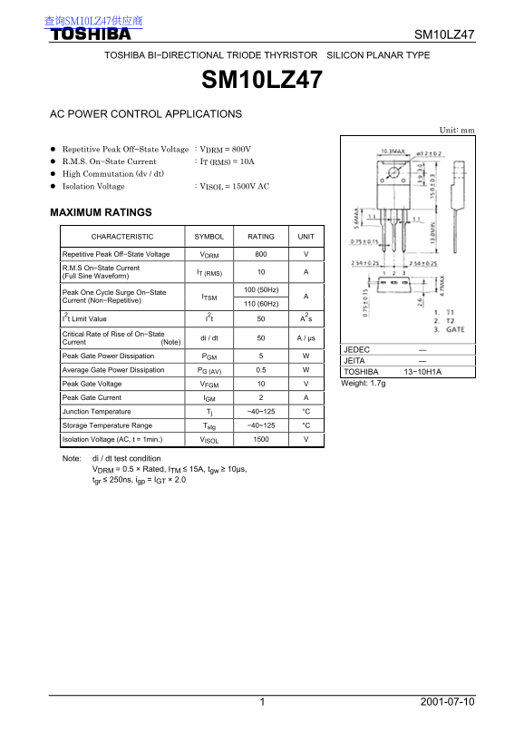
Page 1 Text Content
查询SM10LZ47供应商
SM10LZ47
TOSHIBA BI−DIRECTIONAL TRIODE THYRISTOR SILICON PLANAR TYPE
SM10LZ47
AC POWER CONTROL APPLICATIONS
Unit: mm
Repetitive Peak Off−State Voltage : VDRM = 800V R.M.S. On−State Current : IT (RMS) = 10A High Commutation (dv / dt) Isolation Voltage : VISOL = 1500V AC
MAXIMUM RATINGS
CHARACTERISTIC SYMBOL RATING UNIT
Repetitive Peak Off−State Voltage VDRM 800 V R.M.S On−State Current (Full Sine Waveform) IT (RMS) 10 A
100 (50Hz) Peak One Cycle Surge On−State
Current (Non−Repetitive) ITSM
110 (60Hz)
I2t Limit Value I2t 50 A2s
Critical Rate of Rise of On−State Current (Note) di / dt 50 A / µs
JEDEC ―
Peak Gate Power Dissipation PGM 5 W
JEITA ―
Average Gate Power Dissipation PG (AV) 0.5 W
TOSHIBA 13−10H1A Peak Gate Voltage VFGM 10 V Weight: 1.7g
Peak Gate Current IGM 2 A Junction Temperature Tj −40~125 °C Storage Temperature Range Tstg −40~125 °C Isolation Voltage (AC, t = 1min.) VISOL 1500 V
Note: di / dt test condition VDRM = 0.5 × Rated, ITM ≤ 15A, tgw ≥ 10µs, tgr ≤ 250ns, igp = IGT × 2.0
Page Summary Contents For Toshiba TOSHIBA BI-DIRECTIONAL TRIODE THYRISTOR Silicon Planar Type SM10LZ47 Data Handbook
Manual Details
| Brand | Toshiba |
|---|---|
| Pages | 3 |
| File Size | 86.80 KB |
| Published | June 15, 2026 |
Enter the captcha to get the download link:

Frequently Asked Questions
What is the device's maximum steady-state on-state current?
The R.M.S On−State Current (I_T) rating is 10A for a full sine waveform operating at 100(50Hz).
Are there specific restrictions on where this component can be used?
No. It is not intended or warranted for usage in equipment requiring extraordinarily high quality, such as medical instruments or atomic energy control devices (Unintended Usage).
What are the critical limitations regarding voltage and current rise rates?
The Critical Rate of Rise of Off−State Voltage (dv/dt) is rated at 300 V/µs. The device also handles a minimum di/dt of −5.5A / ms.
What is the safe operating temperature range for this thyristor?
The Junction Temperature (T_j) and Storage Temperature Range (t_stg) are both specified to handle temperatures from -40°C to 125°C.