Texas Instruments CDCLVD110 Programmable Low-Voltage 1-10 LVDS Clock Driver
Summary
This programmable clock driver is engineered for reliable, low-skew distribution of differential LVDS signals across high-speed circuitry. It effectively routes a single pair of differential clock inputs to ten dedicated outputs, making it ideal for controlling 50-Ω transmission line networks. The manual provides comprehensive technical documentation, including electrical characteristics, functional block diagrams, and operating parameters, allowing circuit designers who require precise, programmable clock distribution in digital systems to ensure optimal performance across challenging temperature ranges.
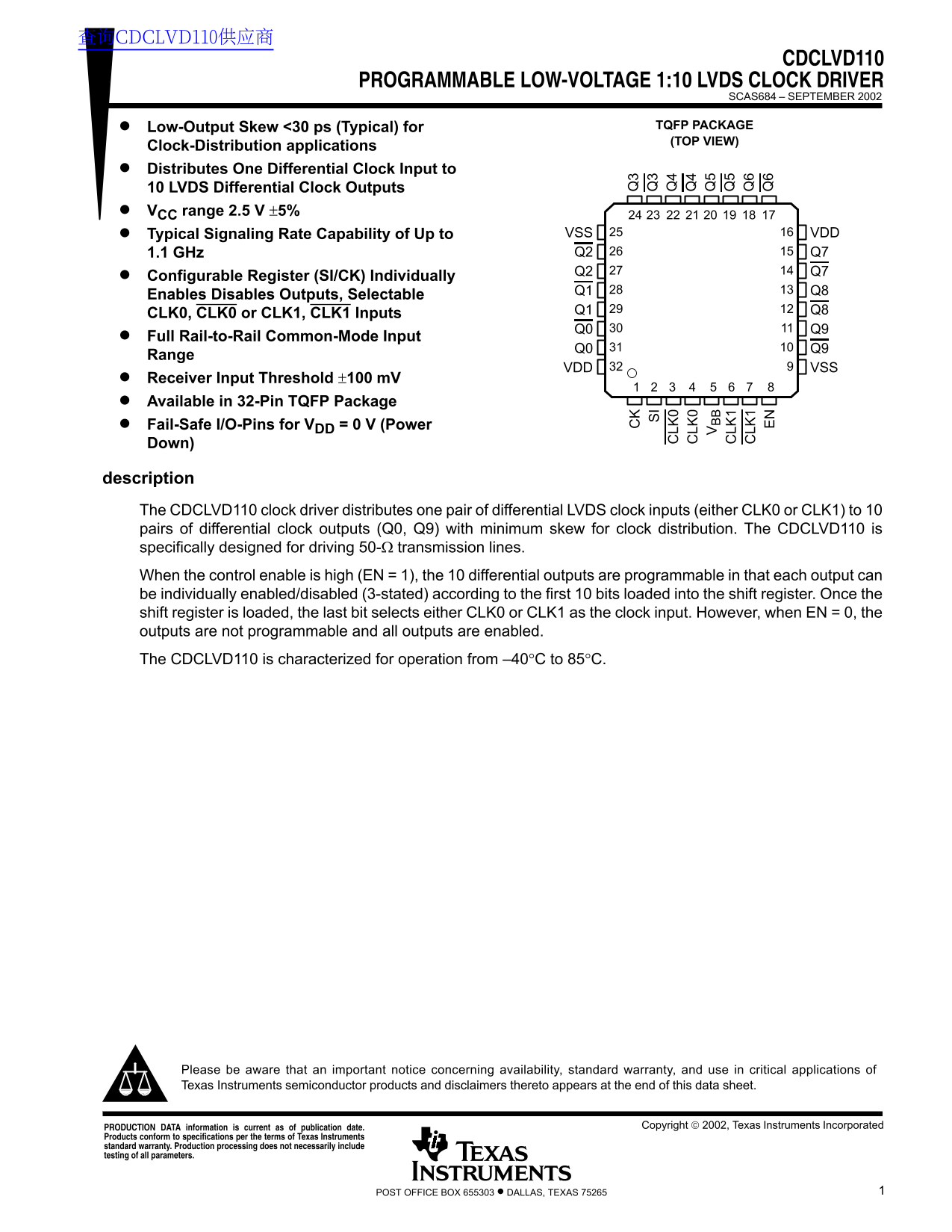
Page 1 Text Content
查询CDCLVD110供应商
CDCLVD110
PROGRAMMABLE LOW-VOLTAGE 1:10 LVDS CLOCK DRIVER
SCAS684 – SEPTEMBER 2002
Low-Output Skew <30 ps (Typical) for TQFP PACKAGE (TOP VIEW)
Clock-Distribution applications Distributes One Differential Clock Input to 10 LVDS Differential Clock Outputs VCC range 2.5 V ±5%
Typical Signaling Rate Capability of Up to VSS VDD 1.1 GHz Q2 Q7
Configurable Register (SI/CK) Individually
Enables Disables Outputs, Selectable
CLK0, CLK0 or CLK1, CLK1 Inputs Q1 Q8
Full Rail-to-Rail Common-Mode Input
Range
VDD VSS
Receiver Input Threshold ±100 m V Available in 32-Pin TQFP Package Fail-Safe I/O-Pins for VDD = 0 V (Power Down)
description The CDCLVD110 clock driver distributes one pair of differential LVDS clock inputs (either CLK0 or CLK1) to 10 pairs of differential clock outputs (Q0, Q9) with minimum skew for clock distribution. The CDCLVD110 is specifically designed for driving 50-Ω transmission lines. When the control enable is high (EN = 1), the 10 differential outputs are programmable in that each output can be individually enabled/disabled (3-stated) according to the first 10 bits loaded into the shift register. Once the shift register is loaded, the last bit selects either CLK0 or CLK1 as the clock input. However, when EN = 0, the outputs are not programmable and all outputs are enabled. The CDCLVD110 is characterized for operation from –40°C to 85°C.
LK LK
LK LK
Please be aware that an important notice concerning availability, standard warranty, and use in critical applications of Texas Instruments semiconductor products and disclaimers thereto appears at the end of this data sheet.
Copyright 2002, Texas Instruments Incorporated PRODUCTION DATA information is current as of publication date.
Products conform to specifications per the terms of Texas Instruments standard warranty. Production processing does not necessarily include testing of all parameters.
1POST OFFICE BOX 655303 • DALLAS, TEXAS 75265
Page Summary Contents For Texas Instruments CDCLVD110 Programmable Low-Voltage 1-10 LVDS Clock Driver
Manual Details
| Brand | Texas Instruments |
|---|---|
| Pages | 10 |
| File Size | 133.61 KB |
| Published | July 15, 2026 |
Enter the captcha to get the download link:

Frequently Asked Questions
What type of signal does the CDCLVD110 distribute?
It distributes LVDS differential clock signals from one pair of inputs (CLK0 or CLK1) to 10 pairs of outputs.
What is the operating temperature range?
The device is characterized for operation from –40°C to 85°C.
What voltage range should be used for optimal performance?
The recommended operating supply voltage (VDD) range is 2.375 V to 2.625 V.