# A B C D E F G H I J K L M N O P Q R S T U V W X Y Z

ST TS556 Low-power Dual CMOS Timer Data Sheet

Summary

The TS556 is a highly efficient dual CMOS timer integrated circuit designed for precision timing applications. It offers robust performance with ultra-low power consumption and high frequency capability across a wide operating voltage range. This guide provides engineers with detailed electrical characteristics, functional parameters, and compatibility information—including simplified decoupling requirements—making it ideal for designing reliable digital circuits, replacing older models while boosting efficiency.
📄 Preview 📖 Table of Contents Contents PAGE OF 19

Page 1 Text Content

TS556

Low-power dual CMOS timer

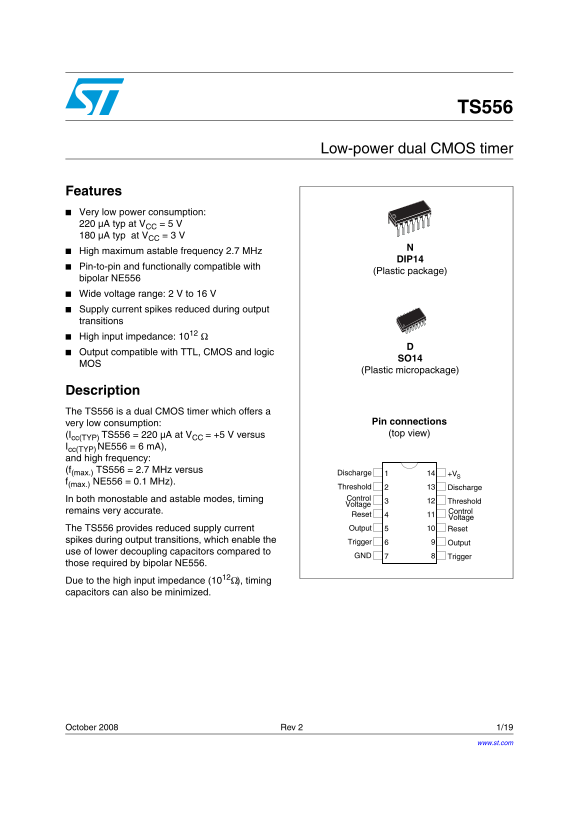
Features Very low power consumption: µA typ at VCC = 5 µA typ at VCC = 3 High maximum astable frequency 2.7 MHz

DIP14

Pin-to-pin and functionally compatible with

(Plastic package)

bipolar NE556 Wide voltage range: 2 V to 16 Supply current spikes reduced during output transitions High input impedance: 1012 Output compatible with TTL, CMOS and logic

(Plastic micropackage)

Description The TS556 is a dual CMOS timer which offers a

very low consumption: Pin connections (Icc(TYP) TS556 = 220 µA at VCC +5 V versus (top view)

Icc(TYP) NE556 = 6 m A), and high frequency: (f(max.) TS556 = 2.7 MHz versus

Discharge +V

f(max.) NE556 = 0.1 MHz).

Threshold Discharge In both monostable and astable modes, timing Control

Threshold

Voltage

remains very accurate. Control

Reset

Voltage

The TS556 provides reduced supply current Output Reset

spikes during output transitions, which enable the Trigger

Output

use of lower decoupling capacitors compared to

GND Trigger

those required by bipolar NE556. Due to the high input impedance (1012Ω), timing capacitors can also be minimized.

October 2008 Rev 2 1/19

www.st.com

Page Summary Contents For ST TS556 Low-power Dual CMOS Timer Data Sheet

Page 1 TS556 Low-power dual CMOS timer Features Very low power consumption: µA typ at VCC = 5 µA typ at VCC = 3 High maximum astable frequency 2.7 MHz DIP14 Pin-to-pin and functionally compatible with (Plast...
Page 2 Absolute maximum ratings and operating conditions TS556 1 Absolute maximum ratings and operating conditions Table 1. Absolute maximum ratings Symbol Parameter Value Unit VCC Supply voltage +18 IOUT Ou...
Page 3 TS556 Schematic diagram 2 Schematic diagram Figure 1. Schematic diagram (1/2 TS556) on tro l V ol ta ge Th re sh ol ut pu ig ge Τ1 Τ2 is ch ar ge R5 Τ1 Τ1 9Tr ES ET
Page 4 Schematic diagram TS556 Figure 2. Block diagram VCC Reset 4 / 10 TS556 Output Threshold Control Voltage Trigger Discharge Ground Table 3. Functions table Reset Trigger Threshold Output Low Low High Lo...
Page 5 TS556 Electrical characteristics 3 Electrical characteristics Table 4. Static electrical characteristics VCC = +2 V, Tamb = +25 °C, Reset to VCC (unless otherwise specified) Symbol Parameter Min. Typ....
Page 6 Electrical characteristics TS556 Table 5. Static electrical characteristics VCC = +3 V, Tamb = +25 °C, Reset to VCC (unless otherwise specified) Symbol Parameter Min. Typ. Max. Unit Supply current (no...
Page 7 TS556 Electrical characteristics Table 6. Dynamic electrical characteristics VCC = +3 V, Tamb = +25 °C, Reset to VCC (unless otherwise specified) Symbol Parameter Min. Typ. Max. Unit Timing accuracy (...
Page 8 Electrical characteristics TS556 Table 7. Static electrical characteristics VCC = +5 V, Tamb = +25 °C, Reset to VCC (unless otherwise specified) Symbol Parameter Min. Typ. Max. Unit Supply current (no...
Page 9 TS556 Electrical characteristics Table 8. Dynamic electrical characteristics VCC = +5 V, Tamb = +25 °C, Reset to VCC (unless otherwise specified) Symbol Parameter Min. Typ. Max. Unit Timing accuracy (...
Page 10 Electrical characteristics TS556 Table 9. Static electrical characteristics VCC = +12 V, Tamb = +25 °C, Reset to VCC (unless otherwise specified) Symbol Parameter Min. Typ. Max. Unit Supply current (n...
Page 11 TS556 Electrical characteristics Figure 3. Supply current (per timer) versus supply voltage CCSUPPLY VOLTAGE, V (V) LY , I
Page 12 Application information TS556 4 Application information 4.1 Monostable operation In the monostable mode, the timer operates like a one-shot generator. Referring to figure 2, the external capacitor is ...
Page 13 TS556 Application information 4.2 Astable operation When the circuit is connected as shown in Figure 6 (pins 2 and 6 connected) it triggers itself and runs as a multivibrator. The external capacitor c...
Page 14 Package information TS556 5 Package information In order to meet environmental requirements, STMicroelectronics offers these devices in ECOPACK® packages. These packages have a lead-free second level ...
Page 15 TS556 Package information 5.1 DIP14 package information Figure 8. DIP14 package mechanical drawing Table 11. DIP14 package mechanical data Dimensions Millimeters Inches Min. Typ. Max. Min. Typ. Max. N...
Page 16 Package information TS556 5.2 SO-14 package information Figure 9. SO-14 package mechanical drawing Table 12. SO-14 package mechanical data Dimensions Millimeters Inches Min. Typ. Max. Min. Typ. Max. 8...
Page 17 TS556 Ordering information 6 Ordering information Table 13. Order codes Order code Temperature range Package Packaging Marking TS556CN DIP14 Tube TS556CN TS556CD 0°C, +70°C Tube or SO-14 556C TS556CDT...
Page 18 Revision history TS556 7 Revision history Table 14. Document revision history Date Revision Changes 01-Feb-2003 Initial release. Document reformatted. Added output current, ESD and thermal resistance ...
Page 19 TS556 Please Read Carefully: Information in this document is provided solely in connection with ST products. STMicroelectronics NV and its subsidiaries (“ST”) reserve the right to make changes, correc...

Manual Details

Brand Dual
Pages 19
File Size 180.65 KB
Published June 03, 2026
50 views

Enter the captcha to get the download link:

captcha

Frequently Asked Questions

How does the TS556 compare to older timers like NE556 in terms of power usage?

The TS556 offers very low consumption, typically drawing 220 µA at V=5V CC, compared to the NE556's typical 6 mA.

Is the TS556 interchangeable with older timers like the NE556 for circuit design?

Yes, it is pin-to-pin and functionally compatible with the bipolar NE556 (plastic package).

What are the available operating temperature ranges for this device?

Temperature options include TS556C (0 to +70°C), TS556I (-40 to +125°C), or TS556M (-55 to +125°C).

How does the TS556 simplify circuit design over previous generations?

It reduces supply current spikes during output transitions, which enables the use of lower decoupling capacitors and minimizes capacitor size overall.