ST L 2-72 6 October 1998 LOW DROP DUAL POWER OPERATIONAL AMPLIFIER
Summary
The L2726 is a versatile low-drop dual power operational amplifier designed for demanding applications like servo amplifiers and motor control circuits. Featuring a high output current of up to 1A, this integrated circuit excels at low-voltage operation while maintaining superior performance with large common-mode rejection and ground-compatible inputs. This manual provides comprehensive technical data, including electrical characteristics, supply voltage configurations, and pin diagrams, making it an essential resource for engineers designing robust power supplies and advanced signal boosting equipment.
Page 1 Text Content
LOW DROP DUAL POWER OPERATIONAL AMPLIFIER
.OUTPUT CURRENT TO A.OPERATES
AT LOW VOLTAGES.SINGLE OR SPLIT SUPPLY.LARGE COMMON-MODE AND
DIFFERENTIAL MODE RANGE.LOW INPUT OFFSET VOLTAGE.GROUND
COMPATIBLE INPUTS.LOW SATURATION VOLTAGE.THERMAL SHUTDOWN.CLAMP DIODE
SO20 (12 4)
ORDERING NUMBER L2726
DESCRIPTION The L2726 is monolithic integratedcircuit in SO-20 packageintended for use as power operationalam- plifiers in widerangeofapplicationsincludingservo amplifiers and powersupplies.
It is particularly indicatedfor driving inductive loads, The high gain and high output powercapability pro- vide superiorperformance whateveran operational
as motor and finds applications in compact-disc
amplifier/power booster combination is required.
VCR automative,etc.
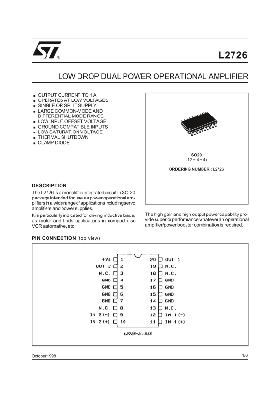
PIN CONNECTION (top view)
October 1/6
This is advanced information on new product now in development or undergoing evaluation. Details are subject to change without notice.
Page Summary Contents For ST L 2-72 6 October 1998 LOW DROP DUAL POWER OPERATIONAL AMPLIFIER
Manual Details
| Brand | Dual |
|---|---|
| Pages | 6 |
| File Size | 64.13 KB |
| Published | May 30, 2026 |
Enter the captcha to get the download link:

Frequently Asked Questions
What is the maximum operating voltage range?
The device supports a single supply voltage of 4V to 28V and split supplies ranging from ±2V to ±14V.
How much power can the unit dissipate at room temperature?
At T = 85°C, the maximum power dissipation is 1W (total ambient).
What safety measure prevents overheating?
The L2726 features a thermal shutdown mechanism, which triggers when the junction temperature reaches 150°C.
What common environmental protection feature is included?
It includes an S$_{O}$ (clamp diode) for overvoltage protection rated at 20V (12 + 4 + 4).
Is this chip suitable for low-power motor applications?
Yes, it performs well in driving inductive loads, making it useful as a servo amplifier or power booster.