# A B C D E F G H I J K L M N O P Q R S T U V W X Y Z

ST TL064 Low power JFET quad operational amplifier Data Handbook

Summary

The TL064 series is a high-speed JFET input operational amplifier designed for demanding signal processing applications. This comprehensive manual details the device's technical performance, covering absolute maximum ratings, operating conditions, and detailed electrical characteristics including low input bias currents, wide voltage ranges, and excellent slew rates (up to 3.5 V/µs). It is essential for electronics designers requiring a reliable, high-performance amplifier with superior stability in compact designs.
📄 Preview 📖 Table of Contents Contents PAGE OF 14

Page 1 Text Content

TL064

Low power JFET quad operational amplifier

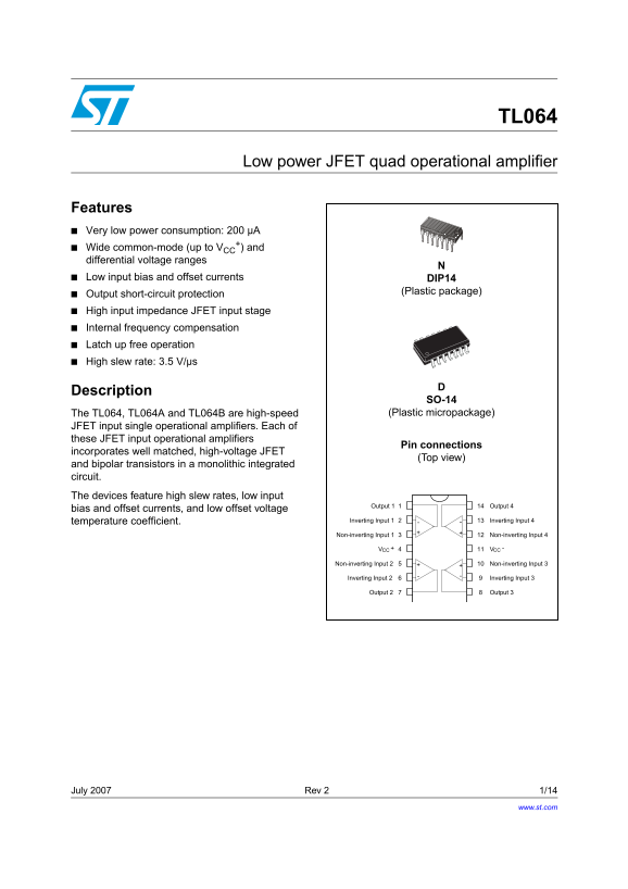
Features Very low power consumption: 200 µA

+) and

Wide common-mode (up to VCC differential voltage ranges Low input bias and offset currents DIP14

(Plastic package)

Output short-circuit protection High input impedance JFET input stage Internal frequency compensation Latch up free operation High slew rate: 3.5 V/µs

Description

SO-14

The TL064, TL064A and TL064B are high-speed (Plastic micropackage)

JFET input single operational amplifiers. Each of these JFET input operational amplifiers

Pin connections

incorporates well matched, high-voltage JFET

(Top view)

and bipolar transistors in a monolithic integrated circuit. The devices feature high slew rates, low input

Output 1 Output 4

bias and offset currents, and low offset voltage

temperature coefficient. Inverting Input 1 Inverting Input 4

Non-inverting Input 1 Non-inverting Input 4

CCV -CCV

Non-inverting Input 2 Non-inverting Input 3

Inverting Input 2 Inverting Input 3

Output 2 Output 3

July 2007 Rev 2 1/14

www.st.com

Page Summary Contents For ST TL064 Low power JFET quad operational amplifier Data Handbook

Page 1 TL064 Low power JFET quad operational amplifier Features Very low power consumption: 200 µA +) and Wide common-mode (up to VCC differential voltage ranges Low input bias and offset currents DIP14 (Pla...
Page 2 Schematic diagram TL064 1 Schematic diagram Figure 1. Circuit schematics Inverting Non-inverting Input Input 1/4 TL064 64Ω Output
Page 3 TL064 Absolute maximum ratings and operating conditions 2 Absolute maximum ratings and operating conditions Table 1. Absolute maximum ratings Value Symbol Parameter Unit TL064M, AM, BM TL064I, AI, BI ...
Page 4 Electrical characteristics TL064 3 Electrical characteristics Table 3. VCC = ±15V, Tamb = +25°C (unless otherwise specified) TL064M TL064I TL064C Unit Symbol Parameter Min. Typ. Max. Min. Typ. Max. Mi...
Page 5 TL064 Electrical characteristics Table 3. VCC = ±15V, Tamb = +25°C (unless otherwise specified) (continued) TL064M TL064I TL064C Unit Symbol Parameter Min. Typ. Max. Min. Typ. Max. Min. Typ. Max. Over...
Page 6 Electrical characteristics TL064 Table 4. VCC = ±15V, Tamb = +25°C (unless otherwise specified) (continued) TL064AC, AI, AM TL064BC, BI, BM Symbol Parameter Unit Min. Typ. Max. Min. Typ. Max. Total po...
Page 7 TL064 Electrical characteristics IF FE EN TI AL LT AG AM PL IF IC AT IO (V /m V) Figure 2. Maximum peak-to-peak output Figure 3. Maximum peak-to-peak output voltage versus supply voltage voltage versu...
Page 8 Electrical characteristics TL064 AL IZ ED NI TY -G AI ND ID TH TO TA PO ER IS SI PA TE AN LE AT SU PP LY EN (μ A) Figure 8. Supply current per amplifier versus Figure 9. Supply current per amplifier v...
Page 9 TL064 Electrical characteristics EQ IV AL EN IN PU NO IS VO LT AG (n V/ VH z) Figure 14. Voltage follower large signal pulse Figure 15. Output voltage versus elapsed time IN PU AN TP VO LT AG ES respo...
Page 10 Typical applications TL064 4 Typical applications Figure 19. Audio distributor amplifier f = 100k Hz O Output A TL064 1μF TL064 Output B Input TL064 1OO μF Output C TL064 5 Package information In orde...
Page 11 TL064 Package information Figure 20. DIP14 package mechanical data Dimensions Ref. Millimeters Inches Min. Typ. Max. Min. Typ. Max.
Page 12 Package information TL064 Figure 21. SO-14 package mechanical data Dimensions Ref. Millimeters Inches Min. Typ. Max. Min. Typ. Max. c1 45° (typ.) 0.68 0.026 8° (max.)
Page 13 TL064 Ordering information 6 Ordering information Table 5. Order codes Temperature Part number Package Packing Marking range TL064MN TL064MN TL064AMN DIP14 Tube TL064AMN TL064BMN TL064BMN TL064MD/MDT ...
Page 14 TL064 Please Read Carefully: Information in this document is provided solely in connection with ST products. STMicroelectronics NV and its subsidiaries (“ST”) reserve the right to make changes, correc...

Manual Details

Brand QUAD
Pages 14
File Size 251.58 KB
Published June 04, 2026
40 views

Enter the captcha to get the download link:

captcha

Frequently Asked Questions

What specialized protections does the TL064 feature?

It incorporates output short-circuit protection, high input impedance JFET stage, and latch up free operation.

What are the maximum voltage limits for differential inputs?

The absolute maximum rating allows a differential input voltage of ±30 V id.

How does the TL064 perform regarding power use?

It consumes very little power, with typical total power consumption listed at 120 mW under no load conditions.

What are the standard temperature ranges for operation?

Operating temperatures vary by package, ranging between -55 to +125 °C or 0 to +70 °C.