ST LM124W LM224W - LM324W LOW POWER QUAD OPERATIONAL AMPLIFIERS Data Manual
Summary
These quad operational amplifiers (op-amps) are engineered for applications requiring high performance within a wide voltage and current spectrum. Featuring low input bias and supply currents, they offer stable signal amplification across both single and dual power supplies, with built-in ESD protection. This comprehensive manual provides technical specifications, electrical characteristics, and package data critical for circuit design, allowing engineers to select the optimal model (LM124W/LM224W/LM324W) for reliable use in demanding analog systems.
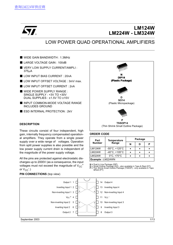
Page 1 Text Content
查询LM224W供应商
LM124W
LM224W - LM324W
LOW POWER QUAD OPERATIONAL AMPLIFIERS
WIDE GAIN BANDWIDTH : 1.3MHz LARGE VOLTAGE GAIN : 100d B VERY LOW SUPPLY CURRENT/AMPLI : 375µA LOW INPUT BIAS CURRENT : 20n A
DIP14 (Plastic Package) (Pl st e)
LOW INPUT OFFSET VOLTAGE : 3m V max. LOW INPUT OFFSET CURRENT : 2n A WIDE POWER SUPPLY RANGE : SINGLE SUPPLY : +3V TO +30V DUAL SUPPLIES : ±1.5V TO ±15V
INPUT COMMON-MODE VOLTAGE RANGE (Plastic Micropackage) INCLUDES GROUND
ESD INTERNAL PROTECTION : 2k V
TSSOP14
DESCRIPTION
(Thin Shrink Small Outline Package)
These circuits consist of four independent, high
gain, internally frequency compensated operation- ORDER CODE
al amplifiers. They operate from a single power
Package
Part Temperature
supply over a wide range of voltages. Operation
Number Range
from split power supplies is also possible and the
low power supply current drain is independent of LM124W -55°C, +125°C the magnitude of the power supply voltage. LM224W -40°C, +105°C LM324W 0°C, +70°C
All the pins are protected against electrostatic dis-
Example : LM224WN
charges up to 2000V (as a consequence, the input
N = Dual in Line Package (DIP)
voltages must not exceed the magnitude of VCC D = Small Outline Package (SO) - also available in Tape & Reel (DT)
P = Thin Shrink Small Outline Package (TSSOP) - only available in Tape
or VCC &Reel (PT)
PIN CONNECTIONS (top view)
September 2003 1/13
Page Summary Contents For ST LM124W LM224W - LM324W LOW POWER QUAD OPERATIONAL AMPLIFIERS Data Manual
Manual Details
| Brand | QUAD |
|---|---|
| Pages | 13 |
| File Size | 608.49 KB |
| Published | May 29, 2026 |
Enter the captcha to get the download link:

Frequently Asked Questions
What are the acceptable power supply voltage ranges for these amplifiers?
They can operate from a single supply of +3V to +30V, or using dual supplies ranging from ±1.5V to ±15V.
How do I determine if this chip is suitable for diverse environmental conditions?
The operation temperature ranges differ by variant: LM124W -55°C to +125°C; LM224W -40°C to +105°C; and LM324W 0°C to +70°C.
What is the maximum output current capability?
The maximum typical output current for both sourcing and sinking directions is between 20mA and 40mA at a supply of V=+15V.
Can these amplifiers handle varying input voltages?
They feature an Input Common-Mode Voltage Range (ICM) spanning from -1.5V to 0V, with the ability to support the full range up to +30V.