# A B C D E F G H I J K L M N O P Q R S T U V W X Y Z

ST LM124W LM224W LM324W Low Power Quad Operational Amplifiers Owner's Manual and User Guide

Summary

These low-power quad operational amplifiers provide four independent, high-gain amplification channels designed for reliability across varied voltage and environmental conditions. The accompanying manual offers comprehensive technical documentation crucial for designers, including detailed absolute maximum ratings, electrical characteristics, multiple package options (DIP, SO, TSSOP), and schematics. It is ideal for signal processing engineers and hardware developers requiring stable, energy-efficient components for portable or robust electronic systems.
📄 Preview PAGE OF 16

Page 1 Text Content

LM124W-LM224W-LM324W

Low Power Quad Operational Amplifiers

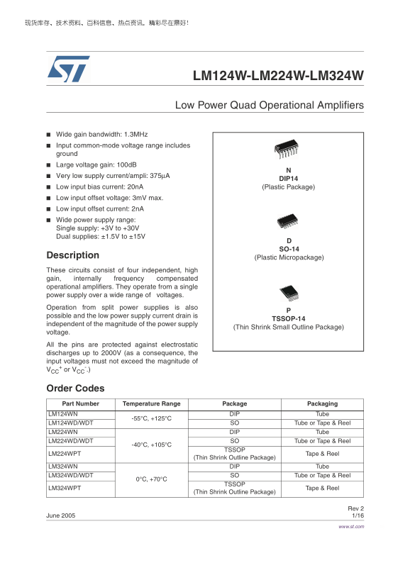
Wide gain bandwidth: 1.3MHz Input common-mode voltage range includes ground Large voltage gain: 100d B Very low supply current/ampli: 375µA

DIP14

Low input bias current: 20n A (Plastic Package) Low input offset voltage: 3m V max. Low input offset current: 2n A Wide power supply range: Single supply: +3V to +30V Dual supplies: ±1.5V to ±15V

SO-14

Description (Plastic Micropackage) These circuits consist of four independent, high gain, internally frequency compensated operational amplifiers. They operate from a single power supply over a wide range of voltages. Operation from split power supplies is also possible and the low power supply current drain is

TSSOP-14

independent of the magnitude of the power supply

(Thin Shrink Small Outline Package)

voltage.

All the pins are protected against electrostatic discharges up to 2000V (as a consequence, the input voltages must not exceed the magnitude of + or VCC VCC

Order Codes Part Number Temperature Range Package Packaging LM124WN DIP Tube

LM124WD/WDT SO Tube or Tape & Reel LM224WN DIP Tube LM224WD/WDT SO Tube or Tape & Reel

TSSOP

LM224WPT Tape & Reel

(Thin Shrink Outline Package)

LM324WN DIP Tube LM324WD/WDT SO Tube or Tape & Reel

TSSOP

LM324WPT Tape & Reel

(Thin Shrink Outline Package)

Rev 2

June 2005 1/16

www.st.com

Page Summary Contents For ST LM124W LM224W LM324W Low Power Quad Operational Amplifiers Owner's Manual and User Guide

Page 1 LM124W-LM224W-LM324W Low Power Quad Operational Amplifiers Wide gain bandwidth: 1.3MHz Input common-mode voltage range includes ground Large voltage gain: 100d B Very low supply current/ampli: 375µA D...
Page 2 Absolute Maximum Ratings LM124W-LM224W-LM324W 1 Absolute Maximum Ratings Table 1. 15Key parameters and their absolute maximum ratings Symbol Parameter LM124W LM224W LM324W Unit VCC Supply voltage ±16 ...
Page 3 LM124W-LM224W-LM324W Pin & Schematic Diagram 2 Pin & Schematic Diagram Figure 1. Pin connections (top view) Figure 2. Schematic diagram (1/4 LM124W)
Page 4 Electrical Characteristics LM124W-LM224W-LM324W 3 Electrical Characteristics + = +5V, VCC -= Ground, Vo = 1.4V, Tamb = +25°C (unless otherwise specified) Table 2. VCC Symbol Parameter Min. Typ. Max. U...
Page 5 LM124W-LM224W-LM324W Electrical Characteristics + = +5V, VCC -= Ground, Vo = 1.4V, Tamb = +25°C (unless otherwise specified) Table 2. VCC Symbol Parameter Min. Typ. Max. Unit High Level Output Voltage...
Page 6 Electrical Characteristics LM124W-LM224W-LM324W Figure 3. Input bias current vs. ambient Figure 4. Current limiting temperature Figure 5. Input voltage range Figure 6. Supply current Figure 7. Gain ba...
Page 7 LM124W-LM224W-LM324W Electrical Characteristics Figure 9. Electrical curves
Page 8 Electrical Characteristics LM124W-LM224W-LM324W Figure 10. Input current Figure 11. Large signal voltage gain Figure 12. Power supply & common mode Figure 13. Voltage gain rejection ratio
Page 9 LM124W-LM224W-LM324W Typical Single - Supply Applications 4 Typical Single - Supply Applications Figure 14. AC coupled inverting amplifier Figure 15. High input Z adjustable gaind DC instrumentation a...
Page 10 Typical Single - Supply Applications LM124W-LM224W-LM324W Figure 20. Activer bandpass filter Figure 21. High input Z, DC differential amplifier R1 R1 R4 100k For C1 330p F (CMRR depends on this resist...
Page 11 LM124W-LM224W-LM324W Macromodels 5 Macromodels Note: Note: Please consider following remarks before using this macromodel: All models are a trade-off between accuracy and complexity (i.e. simulation t...
Page 12 Macromodels LM124W-LM224W-LM324W FIN 5 19 VOFN 3.600000E+02 RG1 19 5 3.652997E+06 RG2 19 4 3.652997E+06 CC 19 5 6.000000E-09 DOPM 19 22 MDTH 400E-12 DONM 21 19 MDTH 400E-12 HOPM 22 28 VOUT 7.500000E+0...
Page 13 LM124W-LM224W-LM324W Package Mechanical Data 6 Package Mechanical Data In order to meet environmental requirements, ST offers these devices in ECOPACK® packages. These packages have a Lead-free second...
Page 14 Package Mechanical Data LM124W-LM224W-LM324W 6.2 SO-14 Package SO-14 MECHANICAL DATA mm. inch MIN. TYP MAX. MIN. TYP. MAX. c1 45˚ (typ.) ˚ (max.) PO13G
Page 15 LM124W-LM224W-LM324W Package Mechanical Data 6.3 TSSOP14 Package TSSOP14 MECHANICAL DATA mm. inch MIN. TYP MAX. MIN. TYP. MAX. 0.65 BSC 0.0256 BSC PIN 1 IDENTIFICATION
Page 16 Revision History LM124W-LM224W-LM324W 7 Revision History Date Revision Changes Sept. 2003 First Release June 2005 ESD protection inserted in Table 1 on page Information furnished is believed to be acc...

Manual Details

Brand QUAD
Pages 16
File Size 791.33 KB
Published May 27, 2026
71 views

Enter the captcha to get the download link:

captcha

Frequently Asked Questions

What is the acceptable operating voltage range for these amplifiers?

For single supplies, the range is +3V to +30V; for dual supplies, it is ±1.5V to ±15V.

Are there any built-in protections against electrical hazards?

Yes, all pins are protected against electrostatic discharges up to 2000V (ESD).

What is the maximum safe power dissipation for these OP-AMPs?

The total specified power dissipation limit is 500 mW for models LM124W, LM224W, and LM324W.

What precautions should be taken when dealing with high voltage output?

If the supply voltage (V) is greater than 15V, short-circuits from the output to VCC can cause excessive heating. The maximum output current is approximately 40mA.