ST EVAL6206Q Dual full bridge with programmable overcurrent Data Sheet User Manual
Summary
Prototype advanced motor control solutions with the EVAL6206Q demonstration board. This system utilizes L6206Q dual full-bridge drivers, enabling you to reliably test applications that require driving single 2-phase stepper motors or up to four DC motors. The manual is a comprehensive guide for developers, providing detailed electrical specifications, pinout diagrams, and clear instructions on integrating the module using PractiSPIN 2 software. Ideal for engineers developing high-performance, configurable motor drive systems.
Page 1 Text Content
EVAL6206Q
Dual full bridge with programmable overcurrent
Data brief
Features Voltage range from 8 V to 52 V Phase current up to 2.5 Ar.m.s. Adjustable overcurrent threshold Logic inputs 5 V / 3.3 V compliant Small application footprint with high thermal performance Suitable for use in combination with Practi SPIN™ 2 software
AM11895v1
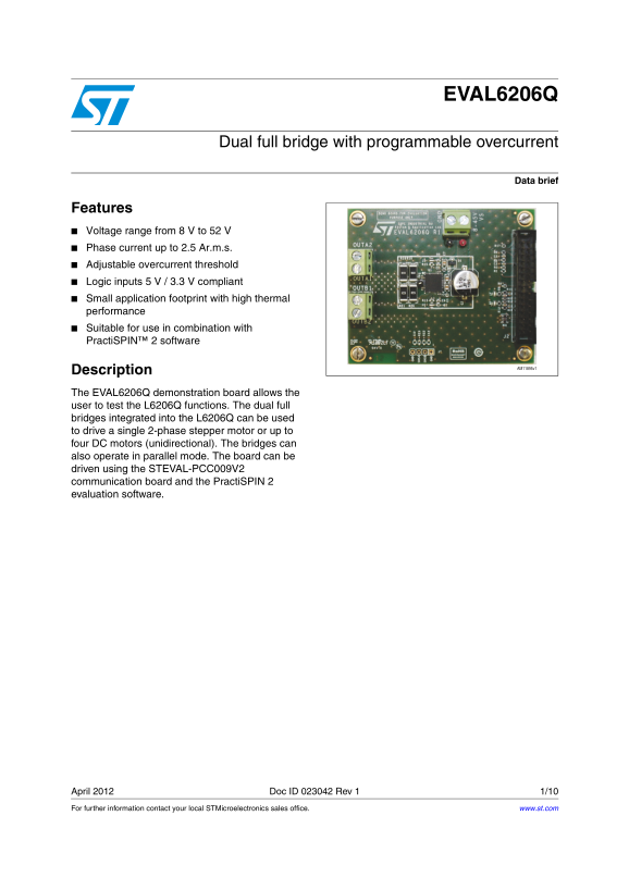
Description The EVAL6206Q demonstration board allows the user to test the L6206Q functions. The dual full bridges integrated into the L6206Q can be used to drive a single 2-phase stepper motor or up to four DC motors (unidirectional). The bridges can also operate in parallel mode. The board can be driven using the STEVAL-PCC009V2 communication board and the Practi SPIN 2 evaluation software.
April 2012 Doc ID 023042 Rev 1 1/10 For further information contact your local STMicroelectronics sales office. www.st.com
Page Summary Contents For ST EVAL6206Q Dual full bridge with programmable overcurrent Data Sheet User Manual
Manual Details
| Brand | Dual |
|---|---|
| Pages | 10 |
| File Size | 1.74 MB |
| Published | June 06, 2026 |
Enter the captcha to get the download link:

Frequently Asked Questions
How many motors can this board drive using the L6206Q bridges?
The dual full bridges can drive a single 2-phase stepper motor or up to four DC motors (unidirectional).
How are current sensing outputs configured?
If using the sense outputs, R22/R23 resistor and C12/C13 capacitor must be added to filter the signal based on your target low-pass frequency.
What is the board's logic input compatibility?
The logic inputs are compliant with both 5 V and 3.3 V systems.