Allegro 3974 DMOS Dual Full-Bridge PWM Motor Driver Data Manual
Summary
The A3974SED is a robust dual full-bridge PWM motor driver designed for precise, current control of two DC motors. Optimized for efficiency, it features synchronous rectification and programmable current-decay modes to minimize power dissipation while managing output currents up to ±1.5A. This technical manual provides detailed electrical characteristics, functional block diagrams, and application guidelines, making it indispensable for electrical engineers designing systems that require reliable and fine-tuned speed and torque control in motor applications.
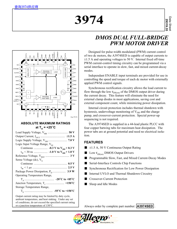
Page 1 Text Content
查询3974供应商 ata S heet 29319.35
DMOS DUAL FULL-BRIDGE PWM MOTOR DRIVER Designed for pulse-width modulated (PWM) current control LO LO
LY LY
of two dc motors, the A3974SED is capable of output currents to
LE LE
±1.5 A and operating voltages to 50 V. Internal fixed off-time
PWM current-control timing circuitry can be programmed via a
NC NC 2B 1B
serial interface to operate in slow, fast, and mixed current-decay
STROBE CP2
PROGRAM modes.
LOGIC
CLOCK PWM TIMER CP1
Independant ENABLE input terminals are provided for use in
DATA CP
controlling the speed and torque of each dc motor with externally
GND GND
applied PWM control signals.
GND GND
GND GND Synchronous rectification circuitry allows the load current to
REF1 OSC flow through the low r DS(on) of the DMOS output driver during
REF2 SLEEP the current decay. This feature will eliminate the need for
PROGRAM
LOGIC
PWM TIMER
LOGIC external clamp diodes in most applications, saving cost and
VDD VREG
SUPPLY
external component count, while minimizing power dissipation.
NC NC
Internal circuit protection includes thermal shutdown with hysteresis, undervoltage monitoring of VDD and the charge pump, and crossover-current protection. Special power-up
Dwg. PP-073
sequencing is not required.
ABSOLUTE MAXIMUM RATINGS The A3974SED is supplied in a 44-lead plastic PLCC with
at TA = +25°C four copper batwing tabs for maximum heat dissipation. The
Load Supply Voltage, VBB 50 V power tabs are at ground potential and need no electrical isola- tion.
Output Current, IOUT ±1.5 A Logic Supply Voltage, VDD 7.0 V
FEATURES
Logic Input Voltage Range, VIN
Continous -0.3 V to VDD + 0.3 V ±1.5 A, 50 V Continuous Output Rating
t W < 30 ns -1.0 V to VDD + 1.0 V
Low r DS(on) DMOS Output Drivers
Reference Voltage, VREF 3 V
Programmable Slow, Fast, and Mixed Current-Decay Modes
Sense Voltage (dc), VS
Continous 0.5 V Serial-Interface Controls Chip Functions
Synchronous Rectification for Low Power Dissipation
Package Power Dissipation, PD 3.9 W
Internal UVLO and Thermal Shutdown Circuitry
Operating Temperature Range,
TA -20°C to +85°C Crossover-Current Protection
Junction Temperature, TJ +150°C
Sleep and Idle Modes
Storage Temperature Range, TS -55°C to +150°C Output current rating may be limited by duty cycle, ambient temperature, and heat sinking. Under any set of conditions, do not exceed the specified current rating or a junction temperature of 150°C.
Always order by complete part number: A3974SED .
Page Summary Contents For Allegro 3974 DMOS Dual Full-Bridge PWM Motor Driver Data Manual
Manual Details
| Brand | Dual |
|---|---|
| Pages | 12 |
| File Size | 160.21 KB |
| Published | June 05, 2026 |
Enter the captcha to get the download link:

Frequently Asked Questions
What modes can I program for current decay control?
You can program Slow, Fast, or Mixed Current-Decay Modes using the serial interface.
Do I need external components like clamp diodes to improve efficiency?
No. Synchronous rectification circuitry eliminates the need for external clamp diodes... while minimizing power dissipation.
Is a specific power-up sequence required when implementing this chip?
No, special power-up sequencing is not required. The unit includes built-in protection circuits.
What are the absolute limits regarding operating temperature and current rating?
The crossover-current protection range is -20°C to +85°C. Never exceed the specified current rating or a junction temperature of 150°C.