Motorola 17517 1.0A 6.8V Dual Motor Driver IC Data Sheet User Manual
Summary
The MPC17517 is a powerful triple totem-pole IC designed for controlling small DC motors and solenoids in portable electronics. This integrated driver features low output MOSFETs, PWM operation up to 200 kHz, and robust protection circuits. The manual provides comprehensive technical data, including operating modes (Forward/Reverse), electrical specifications, interfacing diagrams, and usage guidelines. It is essential for embedded engineers building reliable motion control systems requiring stable operation between 2.0 V and 6.8 V.
Page 1 Text Content
re sc le ic to r,
查询MPC17517供应商 Freescale Semiconductor, Inc. MOTOROLA Document order number: MPC17517
Rev 1.0, 03/2004
SEMICONDUCTOR TECHNICAL DATA
Advance Information
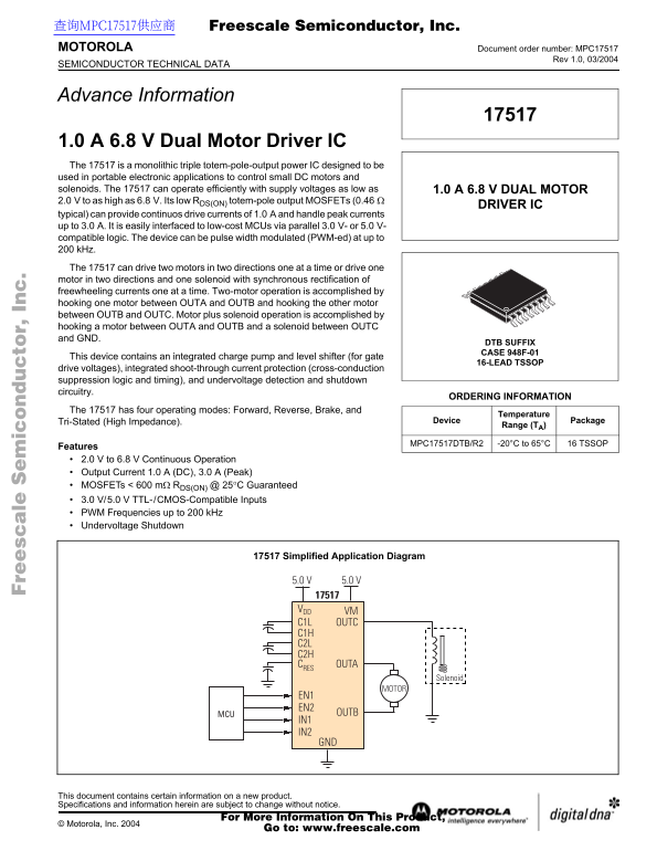
1.0 A 6.8 V Dual Motor Driver IC The 17517 is a monolithic triple totem-pole-output power IC designed to be used in portable electronic applications to control small DC motors and solenoids. The 17517 can operate efficiently with supply voltages as low as 1.0 A 6.8 V DUAL MOTOR 2.0 V to as high as 6.8 V. Its low RDS(ON) totem-pole output MOSFETs (0.46
DRIVER IC
typical) can provide continuos drive currents of 1.0 A and handle peak currents up to 3.0 A. It is easily interfaced to low-cost MCUs via parallel 3.0 V- or 5.0 V- compatible logic. The device can be pulse width modulated (PWM-ed) at up to k Hz. The 17517 can drive two motors in two directions one at a time or drive one motor in two directions and one solenoid with synchronous rectification of freewheeling currents one at a time. Two-motor operation is accomplished by hooking one motor between OUTA and OUTB and hooking the other motor between OUTB and OUTC. Motor plus solenoid operation is accomplished by hooking a motor between OUTA and OUTB and a solenoid between OUTC and GND.
DTB SUFFIX CASE 948F-01
This device contains an integrated charge pump and level shifter (for gate
16-LEAD TSSOP
drive voltages), integrated shoot-through current protection (cross-conduction suppression logic and timing), and undervoltage detection and shutdown circuitry.
ORDERING INFORMATION
The 17517 has four operating modes: Forward, Reverse, Brake, and
Temperature
Tri-Stated (High Impedance). Device Package
Range (TA)
MPC17517DTB/R2 -20°C to 65°C 16 TSSOP
Features 2.0 V to 6.8 V Continuous Operation Output Current 1.0 A (DC), 3.0 A (Peak) MOSFETs < 600 mΩ RDS(ON) @ 25°C Guaranteed 3.0 V/5.0 V TTL-/CMOS-Compatible Inputs PWM Frequencies up to 200 k Hz Undervoltage Shutdown
Simplified Application Diagram 17517 Simplified Application Diagram
VDD VM C1L OUTC C1H C2L C2H CRES OUTA
Solenoid
MOTOR
EN1 EN2 MCU OUTB IN1 IN2 GND
This document contains certain information on a new product. Specifications and information herein are subject to change without notice.
For More Information On This Product,
© Motorola, Inc. 2004
Go to: www.freescale.com
Page Summary Contents For Motorola 17517 1.0A 6.8V Dual Motor Driver IC Data Sheet User Manual
Manual Details
| Brand | Motorola |
|---|---|
| Pages | 12 |
| File Size | 424.34 KB |
| Published | June 04, 2026 |
Enter the captcha to get the download link:

Frequently Asked Questions
What types of loads can the 17517 drive?
It is designed to control small DC motors and solenoids, supporting two-motor operation or one motor and one solenoid simultaneously.
What are the continuous and peak current ratings?
The device provides a continuous drive current of 1.0 A and can handle peak currents up to 3.0 A.
How is dual-motor operation achieved?
Connect one motor between OUTA and OUTB, and connect the second motor between OUTB and OUTC.
What types of control signals are compatible?
It features TTL-/CMOS-compatible inputs using 3.0 V or 5.0 V logic levels.