Motorola MCR218 Series Data Sheet User Manual
Summary
This comprehensive technical manual details the MCR218/D Thyristor, a solid-state Silicon-Controlled Rectifier designed for precise half-wave AC power control applications. Ideal for electrical engineers and designers building motor controls, heating systems, or reliable power supplies, this datasheet provides essential information on voltage ratings (up to 800V), peak surge capabilities, thermal dissipation curves, gate triggering requirements, and package dimensions. Use these specifications for integrating robust, durable power switching components into demanding circuit designs.
Page 1 Text Content
查询MCR218/D供应商
Order this document
SEMICONDUCTOR TECHNICAL DATA by MCR218/D
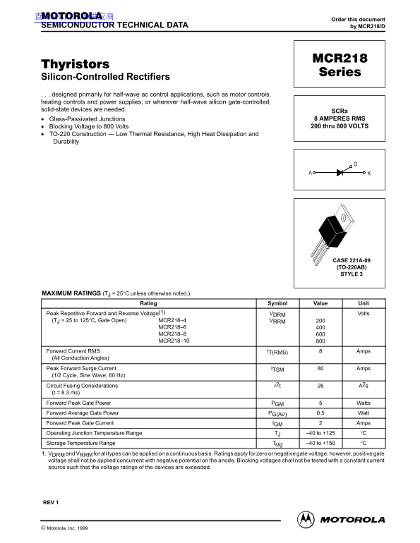
Silicon-Controlled Rectifiers . . . designed primarily for half-wave ac control applications, such as motor controls, heating controls and power supplies; or wherever half-wave silicon gate-controlled, solid-state devices are needed.
SCRs Glass-Passivated Junctions 8 AMPERES RMS Blocking Voltage to 800 Volts 200 thru 800 VOLTS
TO-220 Construction — Low Thermal Resistance, High Heat Dissipation and Durability
CASE 221A-09 (TO-220AB) STYLE 3
MAXIMUM RATINGS (TJ = 25°C unless otherwise noted.)
Rating Symbol Value Unit
Peak Repetitive Forward and Reverse Voltage(1) VDRM Volts (TJ = 25 to 125°C, Gate Open) MCR218–4 VRRM
MCR218–6 MCR218–8 MCR218–10
Forward Current RMS IT(RMS) Amps (All Conduction Angles) Peak Forward Surge Current ITSM Amps (1/2 Cycle, Sine Wave, 60 Hz) Circuit Fusing Considerations I2t A2s (t = 8.3 ms) Forward Peak Gate Power PGM Watts Forward Average Gate Power PG(AV) 0.5 Watt Forward Peak Gate Current IGM Amps Operating Junction Temperature Range TJ –40 to +125 °C Storage Temperature Range Tstg –40 to +150 °C 1. VDRM and VRRM for all types can be applied on a continuous basis. Ratings apply for zero or negative gate voltage; however, positive gate voltage shall not be applied concurrent with negative potential on the anode. Blocking voltages shall not be tested with a constant current source such that the voltage ratings of the devices are exceeded.
REV 1
1Motorola Thyristor Device Data
Motorola, Inc. 1999
Page Summary Contents For Motorola MCR218 Series Data Sheet User Manual
Manual Details
| Brand | Motorola |
|---|---|
| Pages | 4 |
| File Size | 80.62 KB |
| Published | May 31, 2026 |
Enter the captcha to get the download link:
