MOTOROLA MCR506 Series Data Sheet User Guide
Summary
The MCR506 is a robust, high-reliability SCR Thyristor optimized for critical consumer and industrial control applications, including speed, temperature, and light regulation systems. This comprehensive technical manual provides detailed specifications on performance, covering maximum ratings, thermal dissipation curves, and full electrical characteristics. It is essential reading for design engineers and technical professionals selecting reliable power switching components for demanding process or remote monitoring equipment.
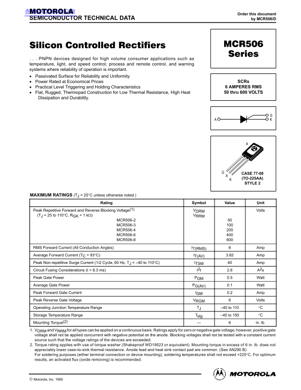
Page 1 Text Content
查询MCR506供应商
Order this document
SEMICONDUCTOR TECHNICAL DATA by MCR506/D
. . . PNPN devices designed for high volume consumer applications such as temperature, light, and speed control; process and remote control, and warning systems where reliability of operation is important. Passivated Surface for Reliability and Uniformity
Power Rated at Economical Prices SCRs Practical Level Triggering and Holding Characteristics 6 AMPERES RMS Flat, Rugged, Thermopad Construction for Low Thermal Resistance, High Heat 50 thru 600 VOLTS
Dissipation and Durability.
CASE 77-08 (TO-225AA) STYLE 2
MAXIMUM RATINGS (TJ = 25°C unless otherwise noted.)
Rating Symbol Value Unit
Peak Repetitive Forward and Reverse Blocking Voltage(1) VDRM Volts
(TJ = 25 to 110°C, RGK = 1 kΩ) VRRM
MCR506-2 MCR506-3 MCR506-4 MCR506-6 MCR506-8
RMS Forward Current (All Conduction Angles) IT(RMS) Amp Average Forward Current (TC = 93°C) IT(AV) 3.82 Amp Peak Non-repetitive Surge Current (1/2 Cycle, 60 Hz, TJ = –40 to 110°C) ITSM Amp Circuit Fusing Considerations (t = 8.3 ms) I2t 2.6 A2s Peak Gate Power PGM 0.5 Watt Average Gate Power PG(AV) 0.1 Watt Peak Forward Gate Current IGM 0.2 Amp Peak Reverse Gate Voltage VRGM Volts Operating Junction Temperature Range TJ –40 to 110 °C Storage Temperature Range Tstg –40 to 150 °C Mounting Torque(2) in. lb. 1. VDRM and VRRM for all types can be applied on a continuous basis. Ratings apply for zero or negative gate voltage; however, positive gate voltage shall not be applied concurrent with negative potential on the anode. Blocking voltages shall not be tested with a constant current source such that the voltage ratings of the devices are exceeded. 2. Torque rating applies with use of torque washer (Shakeproof WD19523 or equivalent). Mounting torque in excess of 6 in. lb. does not appreciably lower case-to-sink thermal resistance. Anode lead and heat sink contact pad are common. (See AN290 B) For soldering purposes (either terminal connection or device mounting), soldering temperatures shall not exceed +225°C. For optimum results, an activated flux (oxide removing) is recommended.
1Motorola Thyristor Device Data
Motorola, Inc. 1995
Page Summary Contents For MOTOROLA MCR506 Series Data Sheet User Guide
Manual Details
| Brand | Motorola |
|---|---|
| Pages | 4 |
| File Size | 88.84 KB |
| Published | May 29, 2026 |
Enter the captcha to get the download link:

Frequently Asked Questions
What is the maximum operating junction temperature range?
The Operating Junction Temperature Range (TO) is -40 to 110 °C.
What is the general mounting instruction for the case 77-08?
Mounting torque applies with the use of a torque washer, and the anode lead and heat sink contact pad are common.
What is the recommended process or materials safety guideline for soldering?
For soldering, temperatures shall not exceed +225°C; an activated flux (oxide removing) is recommended for optimum results.
How does thermal resistance play into device rating?
The Thermal Resistance from Junction to Ambient ($R_{ heta JA}$) must be considered during operation, with typical values provided on the datasheet.