Motorola 17550 Quad H-Bridge Micromotor Driver with DCDC Boost Converter User Manual and Data Sheet
Summary
The MPC17550 is a high-performance quad H-Bridge IC designed for controlling four independent micromotors in portable electronic devices. Featuring integrated DC/DC boost conversion, it ensures reliable operation from 2.5V to 5.5V down to 1.6V. This technical guide provides comprehensive specifications, wiring diagrams, and operational details, making it essential for embedded systems engineers developing precise motor control applications requiring robust power management and high-frequency PWM capability.
Page 1 Text Content
re sc le ic to r,
查询MPC17550供应商 Freescale Semiconductor, Inc. MOTOROLA Document order number: MPC17550
Rev 1.0, 03/2004
SEMICONDUCTOR TECHNICAL DATA
Advance Information
Quad H-Bridge Micromotor Driver with DC/DC Boost Converter
The 17550 is a monolithic quad H-Bridge power IC ideal for portable QUAD H-BRIDGE MICROMOTOR
electronic applications containing tiny bipolar stepper motors and/or brush DRIVER WITH DC/DC BOOST DC-motors powered by two-to-four cell Ni Cd/Ni MH batteries.
CONVERTER
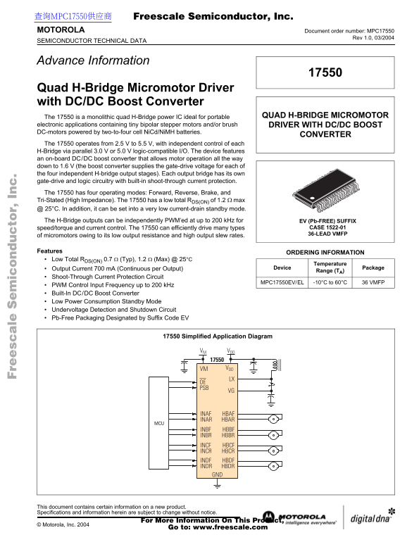
The 17550 operates from 2.5 V to 5.5 V, with independent control of each H-Bridge via parallel 3.0 V or 5.0 V logic-compatible I/O. The device features an on-board DC/DC boost converter that allows motor operation all the way down to 1.6 V (the boost converter supplies the gate-drive voltage for each of the four independent H-bridge output stages). Each output bridge has its own gate-drive and logic circuitry with built-in shoot-through current protection. The 17550 has four operating modes: Forward, Reverse, Brake, and Tri-Stated (High Impedance). The 17550 has a low total RDS(ON) of 1.2 Ω max @ 25°C. In addition, it can be set into a very low current-drain standby mode. The H-Bridge outputs can be independently PWM’ed at up to 200 k Hz for EV (Pb-FREE) SUFFIX
speed/torque and current control. The 17550 can efficiently drive many types CASE 1522-01 36-LEAD VMFP
of micromotors owing to its low output resistance and high output slew rates.
Features ORDERING INFORMATION Low Total RDS(ON) 0.7 Ω (Typ), 1.2 Ω (Max) @ 25°C
Temperature
Output Current 700 m A (Continuous per Output) Device Package
Range (TA)
Shoot-Through Current Protection Circuit
MPC17550EV/EL -10°C to 60°C 36 VMFP
PWM Control Input Frequency up to 200 k Hz Built-In DC/DC Boost Converter Low Power Consumption Standby Mode Undervoltage Detection and Shutdown Circuit Pb-Free Packaging Designated by Suffix Code EV
Simplified Application Diagram 17550 Simplified Application Diagram
VM VDD
VM VDD LX
OE PSB
INAF HBAF INAR HBAR
INBF HBBF INBR HBBR INCF HBCF INCR HBCR INDF HBDF INDR HBDR GND
This document contains certain information on a new product. Specifications and information herein are subject to change without notice.
For More Information On This Product,
© Motorola, Inc. 2004
Go to: www.freescale.com
Page Summary Contents For Motorola 17550 Quad H-Bridge Micromotor Driver with DCDC Boost Converter User Manual and Data Sheet
Manual Details
| Brand | Motorola |
|---|---|
| Pages | 16 |
| File Size | 418.84 KB |
| Published | May 31, 2026 |
Enter the captcha to get the download link:

Frequently Asked Questions
What is the maximum continuous current per H-Bridge output?
The output current is 700 mA continuously for each individual output bridge.
What unique power feature allows low voltage motor operation?
It includes a built-in DC/DC boost converter, which enables motor operation even when the system voltage drops down to 1.6 V.
How are the four H-Bridges independently controlled?
Each bridge has independent control via parallel 3.0 V or 5.0 V logic-compatible I/O pins and dedicated input controls.
What protective features prevent damage during operation?
The device incorporates built-in shoot-through current protection, undervoltage detection, and a low power consumption standby mode.