# A B C D E F G H I J K L M N O P Q R S T U V W X Y Z

ST TDA7851A 4 x 48 W MOSFET quad bridge power amplifier Data Sheet

Summary

The TDA7851A is a high-performance quad bridge MOSFET power amplifier engineered for reliable, professional audio solutions, particularly in car radio systems. Offering exceptional power capabilities and Hi-Fi grade fidelity with built-in protections against shorts and overloads, it ensures stable sound reproduction. This technical manual provides comprehensive documentation covering the product's electrical specifications, application circuits, pin descriptions, and advanced usage guidelines, making it an indispensable resource for audio equipment developers and electronics engineers building automotive-grade sound systems.
📄 Preview 📖 Table of Contents Contents PAGE OF 15

Page 1 Text Content

TDA7851A

4 x 48 W MOSFET quad bridge power amplifier

Datasheet − production data

Features Multipower BCD technology High output power capability: 4 x 48 W/4 Ω Max. 4 x 28 W/4 Ω @ 14.4 V, 1 k Hz, 10 % 4 x 72 W/2 Ω Max. MOSFET output power stage Excellent 2 Ω driving capability

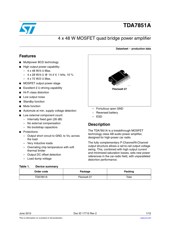
Flexiwatt 27

Hi-Fi class distortion Low output noise Standby function Mute function

Fortuitous open GND

Automute at min. supply voltage detection

Reversed battery

Low external component count:

Internally fixed gain (26 d B) No external compensation

Description

No bootstrap capacitors

The TDA7851A is a breakthrough MOSFET

Protections:

technology class AB audio power amplifier,

Output short circuit to GND, to Vs, across

designed for high-power car radio.

the load

The fully complementary P-Channel/N-Channel

Very inductive loads

output structure allows a rail-to-rail output voltage

Overrating chip temperature with soft

swing. This, combined with high output current

thermal limiter

and minimized saturation losses, sets new power

Output DC offset detection

references in the car-radio field, with unparalleled

Load dump voltage

distortion performance.

Table 1. Device summary

Order code Package Packing

TDA7851A Flexiwatt 27 Tube

June 2012 Doc ID 17715 Rev 2 1/15 This is information on a product in full production. www.st.com

Page Summary Contents For ST TDA7851A 4 x 48 W MOSFET quad bridge power amplifier Data Sheet

Page 1 TDA7851A 4 x 48 W MOSFET quad bridge power amplifier Datasheet − production data Features Multipower BCD technology High output power capability: 4 x 48 W/4 Ω Max. 4 x 28 W/4 Ω @ 14.4 V, 1 k Hz, 10 % ...
Page 2 Contents TDA7851A Contents Block diagram and application circuit . . . . . . . . . . . . . . . . . . . . . . . . . . . 5 1.1 Block diagram . . . . . . . . . . . . . . . . . . . . . . . . . . . . . . ....
Page 3 TDA7851A List of tables List of tables Table 1. Device summary . . . . . . . . . . . . . . . . . . . . . . . . . . . . . . . . . . . . . . . . . . . . . . . . . . . . . . . . . . 1 Table 2. Thermal da...
Page 4 List of figures TDA7851A List of figures Figure 1. Block diagram . . . . . . . . . . . . . . . . . . . . . . . . . . . . . . . . . . . . . . . . . . . . . . . . . . . . . . . . . . . . 5 Figure 2. App...
Page 5 TDA7851A Block diagram and application circuit 1 Block diagram and application circuit 1.1 Block diagram Figure 1. Block diagram 1.2 Application circuit Figure 2. Application circuit Doc ID 17715 Rev ...
Page 6 Pin description TDA7851A 2 Pin description 2.1 Pin connection Figure 3. Pin connection (top view) 2.2 Thermal data Table 2. Thermal data Symbol Parameter Value Unit Rth j-case Thermal resistance junct...
Page 7 TDA7851A Electrical specifications 3 Electrical specifications 3.1 Absolute maximum ratings Table 3. Absolute maximum ratings Symbol Parameter Value Unit VS Operating supply voltage VS (DC) DC supply ...
Page 8 Electrical specifications TDA7851A Table 4. Electrical characteristics (continued) Symbol Parameter Test condition Min. Typ. Max. Unit "A" Weighted µV e No Output noise Bw = 20 Hz to 20 k Hz...
Page 9 TDA7851A Electrical specifications 3.3 Electrical characteristics curves Figure 4. Quiescent current vs. supply Figure 5. Output power vs. supply voltage voltage (RL = 4 Ω) Figure 6. Output power vs. ...
Page 10 Electrical specifications TDA7851A Figure 10. Distortion vs. frequency Figure 11. Crosstalk vs. frequency (RL = 2 Ω) Figure 12. Supply voltage rejection vs. Figure 13. Output attenuation vs. supply fr...
Page 11 TDA7851A Electrical specifications Figure 16. Power dissipation vs. output power Figure 17. Power dissipation vs. output power (RL = 4 Ω, audio program simulation) (RL = 2 Ω, audio program simulation)...
Page 12 Application hints TDA7851A 4 Application hints 4.1 DC offset detector The TDA7851A integrates a DC offset detector to avoid that an anomalous DC offset on the inputs of the amplifier may be multiplied...
Page 13 TDA7851A Package information 5 Package information In order to meet environmental requirements, ST offers these devices in different grades of ECOPACK® packages, depending on their level of environmen...
Page 14 Revision history TDA7851A 6 Revision history Table 5. Document revision history Date Revision Changes 09-Jul-2010 Initial release. Updated Features on page 1; 13-Jun-2012 Updated Section 3.2: Electric...
Page 15 TDA7851A Please Read Carefully: Information in this document is provided solely in connection with ST products. STMicroelectronics NV and its subsidiaries (“ST”) reserve the right to make changes, cor...