# A B C D E F G H I J K L M N O P Q R S T U V W X Y Z

ST STA540SAN 4 x 10-watt dual quad power amplifier Data Sheet User Manual

Summary

This integrated circuit is a high-performance Class-AB audio amplifier designed for sophisticated sound applications requiring reliable, stable power output. The comprehensive manual provides detailed specifications, including absolute maximum ratings, electrical characteristics, and advanced diagnostic facilities such as short-circuit detection and thermal protection. It guides engineers through optimal PCB layout, pairing techniques, and integration using robust tools like the standard applications board. This resource is essential for audio designers building high-quality sound systems that demand reliable anti-pop features and minimal external component count.
📄 Preview 📖 Table of Contents Contents PAGE OF 26

Page 1 Text Content

STA540SAN

4 x 10-watt dual/quad power amplifier

Features High output-power capability: 4 x 9 W / 2 Ω at 12 V, 1 k Hz, 10% 4 x 10 W / 4 Ω at 17 V, 1 k Hz, 10% 2 x 26 W / 4 Ω at 14.4 V, 1 k Hz, 10% 2 x 15 W / 8 Ω at 16 V, 1 k Hz, 10% Minimum external component count:

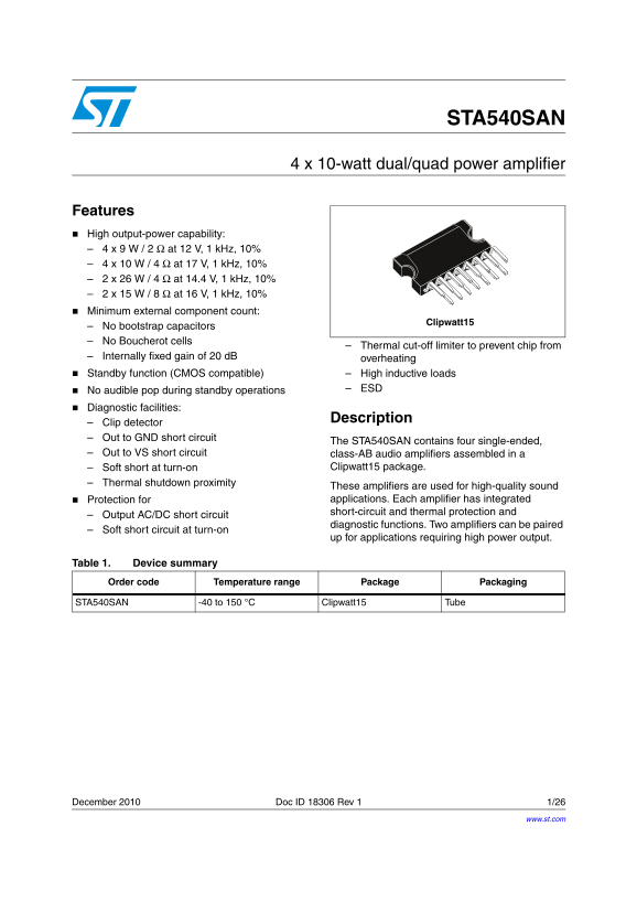
Clipwatt15

No bootstrap capacitors No Boucherot cells

Thermal cut-off limiter to prevent chip from

Internally fixed gain of 20 d B overheating Standby function (CMOS compatible) High inductive loads

No audible pop during standby operations ESD

Diagnostic facilities:

Description

Clip detector Out to GND short circuit

The STA540SAN contains four single-ended,

Out to VS short circuit class-AB audio amplifiers assembled in a

Soft short at turn-on Clipwatt15 package.

Thermal shutdown proximity

These amplifiers are used for high-quality sound Protection for applications. Each amplifier has integrated short-circuit and thermal protection and

Output AC/DC short circuit

diagnostic functions. Two amplifiers can be paired

Soft short circuit at turn-on

up for applications requiring high power output.

Table 1. Device summary Order code Temperature range Package Packaging

STA540SAN -40 to 150 °C Clipwatt15 Tube

December 2010 Doc ID 18306 Rev 1 1/26

www.st.com

Page Summary Contents For ST STA540SAN 4 x 10-watt dual quad power amplifier Data Sheet User Manual

Page 1 STA540SAN 4 x 10-watt dual/quad power amplifier Features High output-power capability: 4 x 9 W / 2 Ω at 12 V, 1 k Hz, 10% 4 x 10 W / 4 Ω at 17 V, 1 k Hz, 10% 2 x 26 W / 4 Ω at 14.4 V, 1 k Hz, 10% 2 x ...
Page 2 Contents STA540SAN Contents Block diagram . . . . . . . . . . . . . . . . . . . . . . . . . . . . . . . . . . . . . . . . . . . . . . 4 Pin description . . . . . . . . . . . . . . . . . . . . . . . . ...
Page 3 STA540SAN Contents Revision history . . . . . . . . . . . . . . . . . . . . . . . . . . . . . . . . . . . . . . . . . . . 25 Doc ID 18306 Rev 1 3/26
Page 4 Block diagram STA540SAN 1 Block diagram Figure 1. Block diagram VCC2 VCC1 1+ OUT1 A2 INV ST_BY A4 INV DIAGNOSTIC IN4 OUTPUT SVR P_GND S_GND D06AU1630_bc 4/26 Doc ID 18306 Rev 1
Page 5 STA540SAN Pin description 2 Pin description Figure 2. Pin connection (top view) OUT3 OUT4 VCC2 IN3 IN4 DIAG S_GND P_GND ST_BY SVR IN2 IN1 VCC1 OUT2 OUT1 clp15_pins_540san_bc Table 2. Pin description P...
Page 6 Electrical specifications STA540SAN 3 Electrical specifications 3.1 Absolute maximum ratings Table 3. Absolute maximum ratings Symbol Parameter Value Unit Supply voltage idle mode (no signal) VSmax Su...
Page 7 STA540SAN Electrical specifications Table 5. Electrical characteristics (continued) Symbol Parameter Test condition Min Typ Max Unit f = 1 k Hz CT Crosstalk d B f = 10 k Hz Rin Input impedance kΩ Gv V...
Page 8 est an ap licatio s b ard 540S 4 Test and applications board This chapter includes information about the test and applications board including the test circuit, board layout, and parts list. Figure 3....
Page 9 STA540SAN Test and applications board Figure 4. Component layout Figure 5. Component side Figure 6. Solder side Doc ID 18306 Rev 1 9/26
Page 10 Test and applications board STA540SAN Table 6. List of components Components Suggested value Purpose R1 kΩ Standby time constant R2 1.8 kΩ Ripple rejection C1, C2, C3, C4 0.22 µF Input AC coupling C5 ...
Page 11 STA540SAN Standard applications circuits 5 Standard applications circuits Figure 7. Quad stereo ST-BY VS Suggested applications: 0.22µF 2200µF OUT1 4 x 12 W at 2 Ω, 14.4 4 x 10 W at 4 Ω, 17 2200µF OUT...
Page 12 Standard applications circuits STA540SAN Figure 10. Stereo Bridge ST-BY VS OUT L 0.22µF 2200µF IN R OUT R IN BRIDGE BRIDGE DIAGNOSTICS D05AU1601 Suggested applications: 2 x 9 W into 2 Ω + 1 x 18 W int...
Page 13 STA540SAN Electrical characteristics curves 6 Electrical characteristics curves Figure 11. Quiescent drain current vs supply Figure 12. Quiescent output voltage vs supply voltage (single-ended and bri...
Page 14 Electrical characteristics curves STA540SAN Figure 17. Output power vs supply voltage Figure 18. Distortion vs output power Figure 19. Output power vs supply voltage Figure 20. Crosstalk vs frequency ...
Page 15 STA540SAN Electrical characteristics curves Figure 23. Supply voltage rejection vs Figure 24. Total power dissipation and frequency efficiency vs output power Figure 25. Total power dissipation and ef...
Page 16 Thermal information STA540SAN 7 Thermal information In order to avoid the thermal protection intervention that is placed at Tj =150 °C (thermal muting) or Tj=160 °C (thermal shutdown), it is important...
Page 17 STA540SAN Thermal information Figure 26. Power derating curve Pd(W) 1) Infinite Tamb(C) Doc ID 18306 Rev 1 17/26
Page 18 General structure STA540SAN 8 General structure 8.1 High application flexibility The availability of four independent channels makes it possible to accomplish several kinds of applications ranging fro...
Page 19 STA540SAN General structure 8.6 Output stage The fully complementary output stage is possible with the power ICV PNP component. This novel design is based on the connection shown in Figure 27 and allo...
Page 20 General structure STA540SAN 8.7 Short-circuit protection Reliable and safe operation in the presence of all kinds of short circuits involving the outputs is assured by built-in protection. Additionall...
Page 21 STA540SAN General structure 8.7.2 Thermal shutdown With the thermal shutdown feature, the output (pin 10) signals the proximity of the junction temperature to the shutdown threshold. Typically, curren...
Page 22 General structure STA540SAN 8.8 Handling of the diagnostic information As different diagnostic information is available at the same pin (clipping detection, output fault, thermal proximity), the signa...
Page 23 STA540SAN General structure 8.9 PCB-layout grounding (general rules) The device has two distinct ground leads, P_GND (power ground) and S_GND (signal ground) which are practically disconnected from ea...
Page 24 Package mechanical data STA540SAN 9 Package mechanical data In order to meet environmental requirements, ST offers these devices in different grades of ECOPACK® packages, depending on their level of e...
Page 25 STA540SAN Revision history 10 Revision history Table 7. Document revision history Date Revision Changes 16-Dec-2010 Initial release Doc ID 18306 Rev 1 25/26
Page 26 STA540SAN Please Read Carefully: Information in this document is provided solely in connection with ST products. STMicroelectronics NV and its subsidiaries (“ST”) reserve the right to make changes, co...

Manual Details

Brand Dual
Pages 26
File Size 692.39 KB
Published June 03, 2026
59 views

Enter the captcha to get the download link:

captcha

Frequently Asked Questions

Does the amplifier require external components for operation?

No, it minimizes external components and eliminates the need for bootstrap capacitors or Boucherot cells.

How does the STA540SAN handle short circuits during use?

It includes diagnostic functions (Pin 10) to detect 'Out to GND' short circuits and 'Out to VS' short circuits, plus general short-circuit protection.

Is pairing multiple amplifiers possible with this module?

Yes, two amplifiers can be paired together for applications requiring high power output.

What is the operating temperature range?

The device has a specified operational temperature range of -40 to 150 °C.