MOTOROLA MMSF5N03HD Data Sheet (1) User Manual
Summary
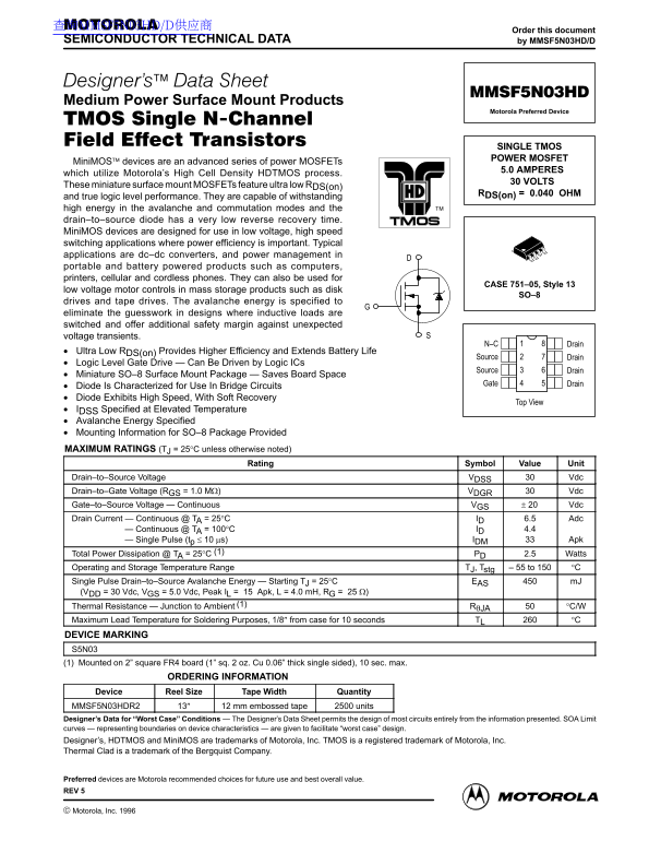
This high-performance MiniMOS Power MOSFET is engineered for superior power efficiency in demanding switching circuits. The comprehensive technical manual provides crucial details on electrical characteristics, thermal guidelines, and packaging suitable for integrating into compact designs. It is the ideal component for engineers developing low voltage, high-speed applications such as DC-DC converters and advanced battery-operated electronics (including mobile phones and computer hardware).
Page 1 Text Content
查询MMSF5N03HD/D供应商
Order this document
SEMICONDUCTOR TECHNICAL DATA by MMSF5N03HD/D
Medium Power Surface Mount Products
Motorola Preferred Device
SINGLE TMOS POWER MOSFET
Mini MOS devices are an advanced series of power MOSFETs
5.0 AMPERES
which utilize Motorola’s High Cell Density HDTMOS process.
30 VOLTS
These miniature surface mount MOSFETs feature ultra low RDS(on)
RDS(on) = 0.040 OHM
and true logic level performance. They are capable of withstanding high energy in the avalanche and commutation modes and the drain–to–source diode has a very low reverse recovery time. Mini MOS devices are designed for use in low voltage, high speed switching applications where power efficiency is important. Typical applications are dc–dc converters, and power management in portable and battery powered products such as computers, printers, cellular and cordless phones. They can also be used for
CASE 751–05, Style 13
low voltage motor controls in mass storage products such as disk
drives and tape drives. The avalanche energy is specified to eliminate the guesswork in designs where inductive loads are switched and offer additional safety margin against unexpected voltage transients.
N–C Drain
Ultra Low RDS(on) Provides Higher Efficiency and Extends Battery Life
Source Drain
Logic Level Gate Drive — Can Be Driven by Logic ICs
Source Drain
Miniature SO–8 Surface Mount Package — Saves Board Space
Gate Drain
Diode Is Characterized for Use In Bridge Circuits Diode Exhibits High Speed, With Soft Recovery
Top View
IDSS Specified at Elevated Temperature Avalanche Energy Specified Mounting Information for SO–8 Package Provided MAXIMUM RATINGS (TJ = 25°C unless otherwise noted)
Rating Symbol Value Unit
Drain–to–Source Voltage VDSS Vdc Drain–to–Gate Voltage (RGS = 1.0 MΩ) VDGR Vdc Gate–to–Source Voltage — Continuous VGS Vdc Drain Current — Continuous @ TA = 25°C ID 6.5 Adc
Drain Current — Continuous @ TA = 100°C ID 4.4 Drain Current — Single Pulse (tp ≤ 10 µs) IDM Apk
Total Power Dissipation @ TA = 25°C (1) PD 2.5 Watts Operating and Storage Temperature Range TJ, Tstg 55 to 150 °C Single Pulse Drain–to–Source Avalanche Energy — Starting TJ = 25°C EAS m J (VDD = 30 Vdc, VGS = 5.0 Vdc, Peak IL = 15 Apk, L = 4.0 m H, RG = 25 Ω) Thermal Resistance — Junction to Ambient (1) RθJA °C/W Maximum Lead Temperature for Soldering Purposes, 1/8″ from case for 10 seconds TL °C DEVICE MARKING S5N03 (1) Mounted on 2” square FR4 board (1” sq. 2 oz. Cu 0.06” thick single sided), 10 sec. max.
ORDERING INFORMATION
Device Reel Size Tape Width Quantity MMSF5N03HDR2 13″ 12 mm embossed tape 2500 units Designer’s Data for “Worst Case” Conditions The Designer’s Data Sheet permits the design of most circuits entirely from the information presented. SOA Limit curves representing boundaries on device characteristics are given to facilitate “worst case” design. Designer’s, HDTMOS and Mini MOS are trademarks of Motorola, Inc. TMOS is a registered trademark of Motorola, Inc. Thermal Clad is a trademark of the Bergquist Company.
Preferred devices are Motorola recommended choices for future use and best overall value. REV 5
1Motorola TMOS Power MOSFET Transistor Device Data
Motorola, Inc. 1996
Page Summary Contents For MOTOROLA MMSF5N03HD Data Sheet (1) User Manual
Manual Details
| Brand | Motorola |
|---|---|
| Pages | 10 |
| File Size | 239.81 KB |
| Published | May 31, 2026 |
Enter the captcha to get the download link:

Frequently Asked Questions
How does this MOSFET improve power efficiency in portable devices?
It utilizes ultra low R DS(on) of 0.040 OHM, offering true logic level performance suitable for high-speed switching applications.
Does the device safely handle unexpected voltage spikes?
Yes, the avalanche energy specification is included to offer an additional safety margin against unexpected voltage transients.
What physical mounting package does this MiniMOS device use?
It features a miniature SO–8 surface mount package, which helps minimize required board space.
What are the supported operating and storage temperature limits?
The continuous operating and storage temperature range for this MOSFET is specified from -55 to 150 °C.