Motorola MC100LVE210 MC100E210 Data Manual (1)
Summary
The MC100LVE210 is a specialized, high-performance dual differential ECL fanout buffer designed for precise clock distribution in demanding backplane and board applications. Featuring two dedicated buffers (1:4 and 1:5), this low-skew device ensures excellent signal integrity by minimizing output skew down to just 50ps. The manual details operational characteristics, emphasizing its ability to manage differential signals across -3.3V supplies while providing critical termination guidelines necessary for reliable high-speed digital system design.
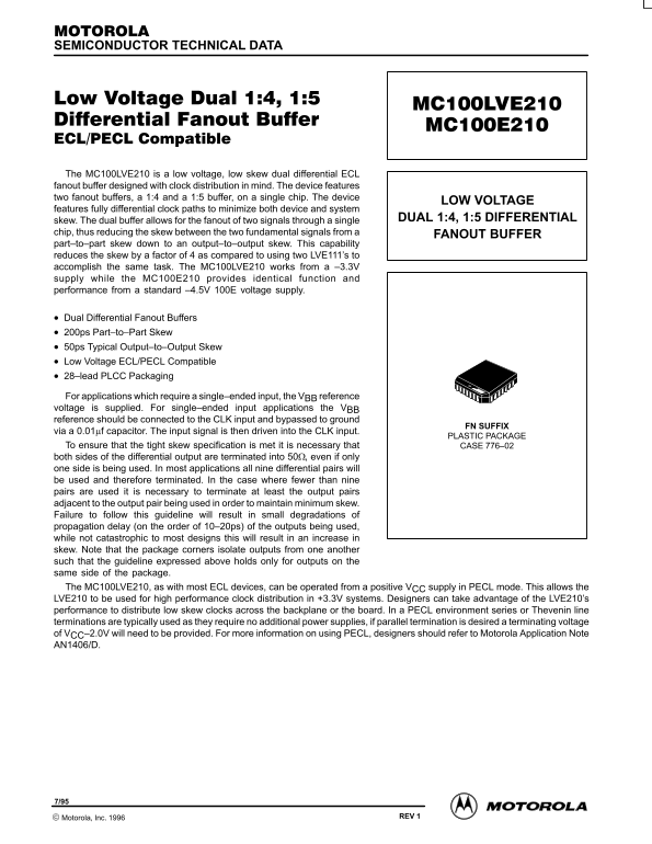
Page 1 Text Content
SEMICONDUCTOR TECHNICAL DATA
LOW VOLTAGE
features fully differential clock paths to minimize both device and system
skew. The dual buffer allows for the fanout of two signals through a single DUAL 1:4, 1:5 DIFFERENTIAL
chip, thus reducing the skew between the two fundamental signals from a FANOUT BUFFER part–to–part skew down to an output–to–output skew. This capability reduces the skew by a factor of 4 as compared to using two LVE111’s to accomplish the same task. The MC100LVE210 works from a –3.3V supply while the MC100E210 provides identical function and performance from a standard –4.5V 100E voltage supply.
Dual Differential Fanout Buffers 200ps Part–to–Part Skew 50ps Typical Output–to–Output Skew Low Voltage ECL/PECL Compatible 28–lead PLCC Packaging
For applications which require a single–ended input, the VBB reference voltage is supplied. For single–ended input applications the VBB reference should be connected to the CLK input and bypassed to ground
FN SUFFIX
via a 0.01µf capacitor. The input signal is then driven into the CLK input.
PLASTIC PACKAGE
To ensure that the tight skew specification is met it is necessary that CASE 776–02 both sides of the differential output are terminated into 50Ω, even if only one side is being used. In most applications all nine differential pairs will be used and therefore terminated. In the case where fewer than nine pairs are used it is necessary to terminate at least the output pairs adjacent to the output pair being used in order to maintain minimum skew. Failure to follow this guideline will result in small degradations of propagation delay (on the order of 10–20ps) of the outputs being used, while not catastrophic to most designs this will result in an increase in skew. Note that the package corners isolate outputs from one another such that the guideline expressed above holds only for outputs on the same side of the package. The MC100LVE210, as with most ECL devices, can be operated from a positive VCC supply in PECL mode. This allows the LVE210 to be used for high performance clock distribution in +3.3V systems. Designers can take advantage of the LVE210’s performance to distribute low skew clocks across the backplane or the board. In a PECL environment series or Thevenin line terminations are typically used as they require no additional power supplies, if parallel termination is desired a terminating voltage of VCC–2.0V will need to be provided. For more information on using PECL, designers should refer to Motorola Application Note AN1406/D.
4–1 REV 1 Motorola, Inc. 1996
Page Summary Contents For Motorola MC100LVE210 MC100E210 Data Manual (1)
Manual Details
| Brand | Motorola |
|---|---|
| Pages | 7 |
| File Size | 79.10 KB |
| Published | May 30, 2026 |
Enter the captcha to get the download link:

Frequently Asked Questions
What is the difference between MC100LVE210 and MC100E210?
MC100LVE210 works from a –3.3V supply, while the MC100E210 provides identical function and performance from a standard –4.5V 100E voltage supply.
How can I ensure minimum skew when terminating outputs?
Terminate CASE 776–02 both sides of the differential output into 50Ω, even if only one side is being used. For fewer than nine pairs, terminate at least the adjacent output pairs.
What components or methods are needed for single-ended input applications?
Supply V reference BB voltage; connect it to the CLK input and bypass it to ground via a 0.01μf capacitor before driving the signal into the CLK input.
Can this device operate in PECL mode?
Yes, the MC100LVE210 can be operated from a positive V supply in PECL mode for high performance clock distribution in +3.3V systems.