# A B C D E F G H I J K L M N O P Q R S T U V W X Y Z

Siemens 1-A Dual-HBD (Dual-Half-Bridge Driver) TLE 4207 User Manual

Summary

This fully protected Dual-Half-Bridge Driver is engineered for robust automotive and industrial motion control applications. It manages DC motors efficiently, providing versatile operational modes including forward, reverse, braking, and high impedance. The comprehensive manual illuminates detailed electrical specifications and built-in safety features such as over/under-voltage lockouts, short circuit protection, and low quiescent current draw, ensuring reliable system integration for demanding industrial environments.
📄 Preview PAGE OF 14

Page 1 Text Content

1-A Dual-HBD (Dual-Half-Bridge Driver) TLE 4207

Overview

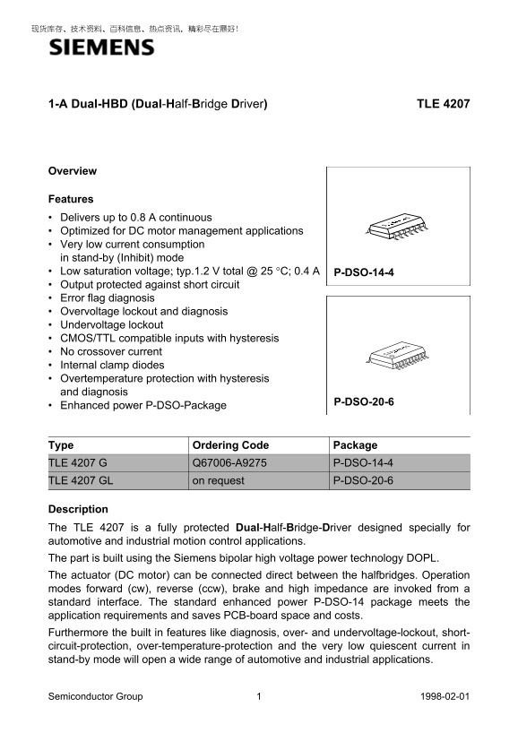
Features Delivers up to 0.8 A continuous Optimized for DC motor management applications Very low current consumption in stand-by (Inhibit) mode Low saturation voltage; typ.1.2 V total @ °C; 0.4 P-DSO-14-4 Output protected against short circuit Error flag diagnosis Overvoltage lockout and diagnosis Undervoltage lockout CMOS/TTL compatible inputs with hysteresis No crossover current Internal clamp diodes Overtemperature protection with hysteresis and diagnosis

P-DSO-20-6

Enhanced power P-DSO-Package

Type Ordering Code Package TLE 4207 G Q67006-A9275 P-DSO-14-4 TLE 4207 GL on request P-DSO-20-6

Description The TLE 4207 is a fully protected Dual-Half-Bridge-Driver designed specially for automotive and industrial motion control applications. The part is built using the Siemens bipolar high voltage power technology DOPL. The actuator (DC motor) can be connected direct between the halfbridges. Operation modes forward (cw), reverse (ccw), brake and high impedance are invoked from a standard interface. The standard enhanced power P-DSO-14 package meets the application requirements and saves PCB-board space and costs. Furthermore the built in features like diagnosis, over- and undervoltage-lockout, short- circuit-protection, over-temperature-protection and the very low quiescent current in stand-by mode will open a wide range of automotive and industrial applications.

Semiconductor Group 1998-02-01

Page Summary Contents For Siemens 1-A Dual-HBD (Dual-Half-Bridge Driver) TLE 4207 User Manual

Page 1 1-A Dual-HBD (Dual-Half-Bridge Driver) TLE 4207 Overview Features Delivers up to 0.8 A continuous Optimized for DC motor management applications Very low current consumption in stand-by (Inhibit) mode...
Page 2 TLE 4207 N.C.SV OUT2 OUT1 VS N.C. OUT2 OUT1 GND GND GND GND TLE GND GND GND GND 4207G GND GND 4207GL GND GND GND GND IN2 IN1 INH EF IN2 IN1 AEP02303 EFINH AEP02304 Figure Pin Configuration (top view) ...
Page 3 TLE 4207 INH Inhibit EF Fault-Detection OUT1 IN2 OUT1IN1INH OUT2 IN1 DRV2 IN2 HL10 LH01 HH11 4207GTLE 10, 11, 12 GND AEB02080 Figure Block Diagram Semiconductor Group 1998-02-01
Page 4 TLE 4207 Functional Truth Table INH IN1 IN2 OUT1 OUT2 Mode 0 X X Z Z Stand-By Brake LL CW CCW Brake HH IN: 0 = Logic LOW OUT: Z = Output in tristate condition 1 = Logic HIGH L = Output in sink conditi...
Page 5 TLE 4207 Electrical Characteristics Absolute Maximum Ratings Parameter Symbol Limit Values Unit Remarks min. max. Voltages Supply voltage VS – 0.3 Supply voltage VS – 1 t < 0.5 s; IS > – 2 A Log...
Page 6 TLE 4207 Operating Range Parameter Symbol Limit Values Unit Remarks min. max. Supply voltage VS VUV After VS rising above VUV Supply voltage increasing VS – 0.3 VUV Outputs in tristate Supply voltage ...
Page 7 TLE 4207 Electrical Characteristics 8 V < VS < 18 V; INH = High; IOUT1-2 = 0 A; – 40 °C < Tj < 150 °C; unless otherwise specified Parameter Symbol Limit Values Unit Test Condition min. typ...
Page 8 TLE 4207 Electrical Characteristics (cont’d) 8 V < VS < 18 V; INH = High; IOUT1-2 = 0 A; – 40 °C < Tj < 150 °C; unless otherwise specified Parameter Symbol Limit Values Unit Test Condition...
Page 9 TLE 4207 Electrical Characteristics (cont’d) 8 V < VS < 18 V; INH = High; IOUT1-2 = 0 A; – 40 °C < Tj < 150 °C; unless otherwise specified Parameter Symbol Limit Values Unit Test Condition...
Page 10 TLE 4207 Electrical Characteristics (cont’d) 8 V < VS < 18 V; INH = High; IOUT1-2 = 0 A; – 40 °C < Tj < 150 °C; unless otherwise specified Parameter Symbol Limit Values Unit Test Condition...
Page 11 TLE 4207 Watchdog Reset TLE 4268G = 12 V SV DO1 1N4001 RQ CQ CD CS WD VS Inhibit EF OUT1 Fault-Detection IN2 OUT1IN1INH OUT2 LL00 OUT2 HL10 LH01 HH11 4207GTLE AES02081 Figure Application Circuit Semic...
Page 12 TLE 4207 Diagrams Quiescent current IS Saturation Voltage of Source VSAT U over Temperature over Temperature AED02307 AED02308 SΙ SAT UV = 14 VSV = 800 m A OUT = 400 m AOUTΙ = 200 m AOUTΙ VS = 18 V = ...
Page 13 TLE 4207 Package Outlines P-DSO-14-4 (Plastic Dual Small Outline Package) 1. ax Index Marking .0 1) Does not include plastic or metal protrusion of 0.15 max. per side 2) Does not include dambar protru...
Page 14 TLE 4207 P-DSO-20-6 (Plastic Dual Small Outline Package) 2. ax GPS05094 Index Marking 1) Does not include plastic or metal protrusions of 0.15 max per side 2) Does not include dambar protrusion of 0.0...

Manual Details

Brand Siemens
Pages 14
File Size 103.99 KB
Published May 29, 2026
60 views

Enter the captcha to get the download link:

captcha

Frequently Asked Questions

What operational modes can this driver support for a DC motor?

It supports forward (cw), reverse (ccw), brake, and high impedance operation modes.

How is the device put into stand-by mode?

The Inhibit (INH) input must be set to logic low (LOW) to place the IC in stand-by mode.

What key protections are built into the TLE 4207?

It offers short circuit protection, overvoltage/undervoltage lockout, and over-temperature protection with diagnosis.

What is the maximum continuous output current capability?

The device delivers up to 0.8 A of continuous output current.