Infineon TDA21106 High Speed Driver with Bootstrapping for Dual Power MOSFETs - Data Sheet
Summary
The TDA21106 is a high-speed dual gate driver designed for controlling N-Channel MOSFETs in half-bridge circuits. This datasheet provides comprehensive technical details on its performance, making it ideal for circuit designers building high-efficiency, multi-phase synchronous DC/DC converters. It offers adaptive gate drive control and bootstrap functionality, perfect for demanding applications such as motherboard VRMs, CPU power supplies, motor drives, and advanced Class-D amplifiers.
Page 1 Text Content
Core Control TM Data Sheet TDA21106
High speed Driver with bootstrapping for dual Power MOSFETs
P-DSO-8
Features
• Fast rise and fall times for frequencies up to 2 MHz • Capable of sinking more than 4A peak currents for lowest switching losses • Charges High Side MOSFET gate drive voltage from 6 to 12V according to PVCC setting; Low Side MOSFET at 12 V. • Adjustable High Side MOSFET gate drive voltage via PVCC pin for optimizing ON losses and gate drive losses • Integrates the bootstrap diode for reducing the part count • Prevents from cross-conducting by adaptive gate drive control • High voltage rating on Phase node • Supports shut-down mode for very low quiescent current through three-state input • Compatible to standard PWM controller ICs (Intersil, Analog Devices) • Floating High Side MOSFET drive • Footprint compatible to TDA21101G and HIP6601B • Ideal for multi-phase Desktop CPU supplies on motherboards and VRM´s
Type Package Marking Ordering Code TDA21106 P-DSO-8 21106 Q67042-S4223
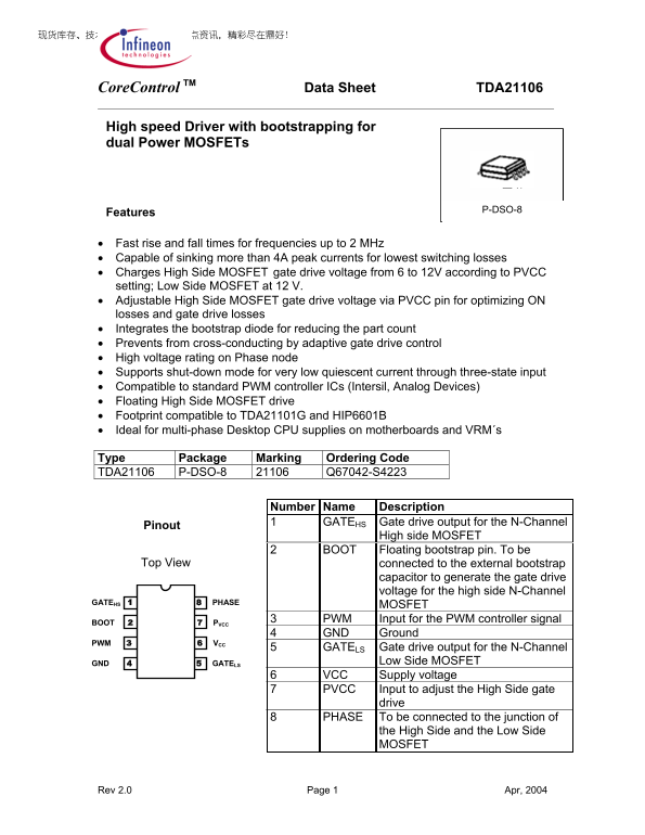
Number Name Description 1 GATEHS Gate drive output for the N-Channel
Pinout
High side MOSFET
2 BOOT Floating bootstrap pin. To be
Top View connected to the external bootstrap
capacitor to generate the gate drive voltage for the high side N-Channel
GATEHS 1 8 PHASE
MOSFET
3 PWM Input for the PWM controller signal
BOOT 2 7 PVCC
4 GND Ground
PWM 3 6 VCC
5 GATELS Gate drive output for the N-Channel
GND 4 5 GATELS Low Side MOSFET
6 VCC Supply voltage 7 PVCC Input to adjust the High Side gate
drive
8 PHASE To be connected to the junction of
the High Side and the Low Side MOSFET
Rev 2.0 Page 1 Apr, 2004
Page Summary Contents For Infineon TDA21106 High Speed Driver with Bootstrapping for Dual Power MOSFETs - Data Sheet
Manual Details
| Brand | Dual |
|---|---|
| Pages | 7 |
| File Size | 213.53 KB |
| Published | May 30, 2026 |
Enter the captcha to get the download link:

Frequently Asked Questions
What types of circuitry can this high-speed driver support?
It is ideal for half-bridge type circuits and multi-phase converters used in CPU supplies, VRMs, motor drives, and Class-D amplifiers.
How do I tune the gate drive voltage settings?
You can adjust the High Side MOSFET gate drive voltage using the dedicated PVCC pin to optimize ON losses and gate drive losses.
What are the operating temperature limitations?
The junction temperature (Tj) must operate between -25 °C and 150 °C for normal functioning.