National Semiconductor LM3407 350mA Constant Current Output Floating Buck Switching Converter for High Power LEDs Data Manual
Summary
The LM3407 is a precision constant current floating buck switching converter designed to efficiently power high-power LED strings. This manual provides comprehensive technical documentation covering device operation, connection diagrams, and advanced features such as adjustable dimming control via PWM and robust protection circuits (UVLO, thermal shutdown). It is the ideal solution for professional engineers designing stable, reliable lighting systems in automotive, industrial, and general illumination applications.
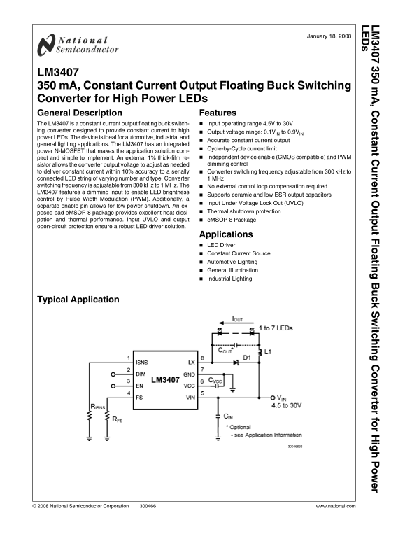
Page 1 Text Content
, C ta t C rre t O tp t F lo tin itc in rte r fo r H ig
January 18, 2008
LM3407 350 m A, Constant Current Output Floating Buck Switching Converter for High Power LEDs General Description Features The LM3407 is a constant current output floating buck switch- Input operating range 4.5V to 30V ing converter designed to provide constant current to high
Output voltage range: 0.1VIN to 0.9VIN
power LEDs. The device is ideal for automotive, industrial and
Accurate constant current output
general lighting applications. The LM3407 has an integrated
Cycle-by-Cycle current limit
power N-MOSFET that makes the application solution com-
pact and simple to implement. An external 1% thick-film re- Independent device enable (CMOS compatible) and PWM sistor allows the converter output voltage to adjust as needed dimming control
to deliver constant current within 10% accuracy to a serially Converter switching frequency adjustable from 300 k Hz to connected LED string of varying number and type. Converter 1 MHz switching frequency is adjustable from 300 k Hz to 1 MHz. The No external control loop compensation required LM3407 features a dimming input to enable LED brightness
Supports ceramic and low ESR output capacitors
control by Pulse Width Modulation (PWM). Additionally, a
Input Under Voltage Lock Out (UVLO)
separate enable pin allows for low power shutdown. An ex-
posed pad e MSOP-8 package provides excellent heat dissi- Thermal shutdown protection
pation and thermal performance. Input UVLO and output e MSOP-8 Package open-circuit protection ensure a robust LED driver solution.
Applications LED Driver Constant Current Source Automotive Lighting General Illumination Industrial Lighting
Typical Application
© 2008 National Semiconductor Corporation www.national.com
Page Summary Contents For National Semiconductor LM3407 350mA Constant Current Output Floating Buck Switching Converter for High Power LEDs Data Manual
Manual Details
| Brand | High Power |
|---|---|
| Pages | 16 |
| File Size | 373.91 KB |
| Published | May 28, 2026 |
Enter the captcha to get the download link:

Frequently Asked Questions
How do I adjust the brightness of the LED string?
Apply a logic level PWM signal to the DIM pin.
What is the supported input voltage range for this device?
The operating input voltage must be between 4.5V and 30V.
Does the LM3407 have protection against low input power?
Yes, it includes an Input Under Voltage Lock-out (UVLO) circuit.
What capacitor specifications are required for the VCC output pin?
It requires a high quality X5R or X7R ceramic capacitor with a minimum value of 1µF.