ST STEVAL-ILL023V1 Demonstration board high-efficiency switching LED driver for high-current LEDs based on the L6726A
Summary
The STEVAL-ILL023V1 is a sophisticated demonstration board designed for engineers developing high-power LED lighting solutions. Utilizing an L6726A PWM controller and synchronous rectification, this module provides exceptionally high efficiency—critical for demanding high-current applications. It supports regulated output across 8V to 18V inputs, while offering scalable control for various LED currents (up to several amps). Its advanced features include precise analog dimming capabilities and safety improvements via MOSFET-based current limitation, making it an ideal, reliable platform for complex industrial and commercial lighting systems requiring optimal performance and longevity.
Page 1 Text Content
STEVAL-ILL023V1
Demonstration board: high-efficiency switching LED driver for
high-current LEDs based on the L6726A
Data Brief
Features Input voltage Vin: 8 V to 18 V Output voltage (with Vin = 18 V): 2.5 V to 14 V Output current ILED: 1 A / 1.5 A / 2.8 A Analog dimming (with ILED= 0 A): 0 V to 2.5 V Low level PWM signal: 0 V High level PWM signal: 2.8 V to 3.8 V (typ: 3.3 V) Duty cycle (at fdim = 200 Hz): 0% to 99 % Efficiency (with Vin = 18 V and Vout = 12.6 V): 94.8 %
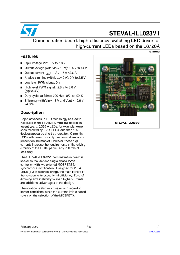
Description Rapid advances in LED technology has led to increases in their output current capabilities in STEVAL-ILL023V1 recent years. 0.350 A LEDs, for example, were soon followed by 0.7 A LEDs, and then 1 A devices appeared shortly thereafter. Currently, LEDs with currents as high as several amps are present on the market. However, these high currents increase the requirements of the driving circuitry of the LEDs, particularly in terms of efficiency. The STEVAL-ILL023V1 demonstration board is based on the L6726A single phase PWM controller, with two external MOSFETS for synchronous rectification. Designed for 2.8 A LEDs (1-3 in a series string), the main benefit of the solution is its exceptional efficiency. Ease of dimming and scalability to even higher currents are additional advantages of the design. The solution is also much safer with regard to border conditions, since the current limit is based solely on the selection of the MOSFETS.
February 2009 Rev 1 1/4 For further information contact your local STMicroelectronics sales office. www.st.com
Page Summary Contents For ST STEVAL-ILL023V1 Demonstration board high-efficiency switching LED driver for high-current LEDs based on the L6726A
Manual Details
| Brand | Current |
|---|---|
| Pages | 4 |
| File Size | 128.50 KB |
| Published | June 03, 2026 |
Enter the captcha to get the download link:

Frequently Asked Questions
What is the input voltage range for this demonstration board?
The STEVAL-ILL023V1 accepts an input voltage range of 8 V to 18 V.
How can I dim my LEDs using this board?
It supports analog dimming (with I = 0 A) ranging from 0 V to 2.5 V, and also provides a low level PWM signal for control.
Can this board be used with high current LEDs?
It can scale to even higher currents and was specifically designed for 2.8 A LEDs (1-3 in a series string).
What safety feature relates to the current limit on this design?
The solution is safer regarding border conditions because the current limit is based solely on the selection of the MOSFETs.