National Semiconductor LM2753 High Power Switched Capacitor Voltage Convertor Flash LED Driver
Summary
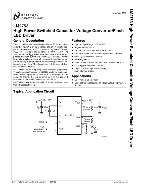
The LM2753 is an advanced, inductor-less switched capacitor voltage converter designed for robust high-power flash LED driving and stable regulated output. It provides reliable 5V regulation and powerful pulsing capabilities, making it ideal for portable devices like cameras or specialized lighting systems. This manual serves as a comprehensive guide for engineers, detailing full electrical specifications, pin definitions (LLP-10 package), operational parameters, typical application circuits, and handling low-power states down to <1µA.
Page 1 Text Content
ig r S itc ito r V lta rto r/F la riv
November 2006
LM2753 High Power Switched Capacitor Voltage Convertor/Flash LED Driver General Description Features The LM2753 is capable of driving a Flash LED with a pulsed Input Voltage Range: 3.0V to 5.5V current of 400m A at an input voltage of 3.6V. A switched ca-
Regulated 5V Output
pacitor doubler, the LM2753 provides a regulated 5V output
250m A Output Current with a 3.6V input
(VOUT) over an input supply range of 3.0V to 5.5V. The
400m A Pulsed Output Current (up to 500ms duration)
switched output, IOUT, takes less than 10ns to turn on and
provide maximum current to a Flash LED. Flash LED current 60µA (typ.) Quiescent Current
is set via a ballast resistor. Continuous illumination current PFM Regulation (Torch Mode) is programmed by connecting a resistor be-
Inductor-less solution: requires only 3 small capacitors
tween IOUT and VOUT. This device uses only three small, low-
<1µA Typical Shutdown Current
cost ceramic capacitors.
10-pin LLP Package (No Pullback):
LM2753 uses Pulse Frequency Modulation (PFM) regulation.
3mm x 3mm x 0.8mm
Typical operating frequency is 725k Hz. Under no-load condi- tions, LM2753 operates on only 60µA. If the output is con-
Applications
nected to ground, the charge pump stays in the gain of 1 which helps limit the input current to 300m A (typ.) Cell Phone Camera Flash LM2753 is available in a 10-pin No Pullback Leadless Lead- General Purpose Regulated Voltage Output, High Current frame Package: LLP-10. Supply
Typical Application Circuit
© 2006 National Semiconductor Corporation www.national.com
Page Summary Contents For National Semiconductor LM2753 High Power Switched Capacitor Voltage Convertor Flash LED Driver
Manual Details
| Brand | High Power |
|---|---|
| Pages | 12 |
| File Size | 1.15 MB |
| Published | May 28, 2026 |
Enter the captcha to get the download link:

Frequently Asked Questions
What is the optimal input voltage range for the LM2753?
The device accepts an Input Voltage Range from 3.0V to 5.5V.
How does the LM2753 operate in a continuous duty cycle (Torch Mode)?
It uses Pulse Frequency Modulation (PFM) regulation and requires connecting a ballast resistor.
What is the peak current capacity for flashing an LED?
The device can provide up to 400mA pulsed output current, lasting for up to 500ms.
How do I manually enable or disable the unit?
Use the Enable Pin (EN): Logic HIGH keeps it enabled; Logic LOW shuts it down.