ST M74HC123 Dual Retriggerable Monostable Multi-Vibrator Data Sheet User Manual
Summary
The M74HC123 is a high-speed CMOS dual retriggerable monostable multivibrator designed for reliable digital timing applications. This manual provides comprehensive technical documentation, covering its operational principles, electrical specifications (including high noise immunity and low power consumption), detailed truth tables, and connectivity diagrams across various packages (DIP/TSSOP). Ideal for engineers and embedded systems designers who require precise, controlled pulse-width generation and versatile triggering mechanisms to enhance circuit timing functions.
Page 1 Text Content
M74HC123
DUAL RETRIGGERABLE MONOSTABLE MULTIVIBRATOR
HIGH SPEED : t PD = 23 ns (TYP.) at VCC = 6V LOW POWER DISSIPATION: STAND BY STATE : ICC=4µA (MAX.) at TA=25°C ACTIVE STATE : ICC=200µA (MAX.) at VCC = 5V SOP TSSOPDIP HIGH NOISE IMMUNITY: VNIH = VNIL = 28 % VCC (MIN.) SYMMETRICAL OUTPUT IMPEDANCE:
ORDER CODES
|IOH| = IOL = 4m A (MIN)
PACKAGE TUBE T & R
BALANCED PROPAGATION DELAYS:
t PLH ≅ t PHL DIP M74HC123B1R WIDE OPERATING VOLTAGE RANGE: SOP M74HC123M1R M74HC123RM13TR VCC (OPR) = 2V to 6V TSSOP M74HC123TTR
WIDE OUTPUT PULSE WIDTH RANGE : t WOUT = 120 ns ~ 60 s OVER AT VCC = 4.5 V
period determined by the external resistor Rx and
PIN AND FUNCTION COMPATIBLE WITH
capacitor Cx. When Cx > 10n F and Rx > 10KΩ,
74 SERIES 123
the output pulse width value is approsimatively given by the formula : t W(OUT) = K · Cx · Rx.
DESCRIPTION (K ≅ 0.45).
The M74HC123 is an high speed CMOS Taking CLR low breaks this MONOSTABLE MONOSTABLE MULTIVIBRATOR fabricated with STATE. If the next trigger pulse occurs during the silicon gate C2MOS technology. MONOSTABLE period it makes the There are two trigger inputs, A INPUT (negative MONOSTABLE period longer. Limit for values of edge) and B INPUT (positive edge). These inputs Cx and Rx : Cx : NO LIMIT are valid for slow rising/falling signals, (tr=tf=l sec). Rx : Vcc < 3.0V 5KΩ to 1MΩ The device may also be triggered by using the Vcc > 3.0V 1KΩ to 1MΩ
CLR input (positive-edge) because of the All inputs are equipped with protection circuits Schmitt-trigger input; after triggering the output against static discharge and transient excess maintains the MONOSTABLE state for the time voltage.
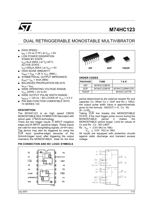
PIN CONNECTION AND IEC LOGIC SYMBOLS
1/12July 2001
Page Summary Contents For ST M74HC123 Dual Retriggerable Monostable Multi-Vibrator Data Sheet User Manual
Manual Details
| Brand | Dual |
|---|---|
| Pages | 12 |
| File Size | 508.07 KB |
| Published | May 31, 2026 |
Enter the captcha to get the download link:
