Siemens BFP 490 User Guide and Specifications (1)(1)
Summary
This comprehensive technical datasheet features the BFP490 Silicon RF Transistor, a specialized component designed for demanding high-power amplifier and ultra-high-frequency applications ($f_T > 17$ GHz). The manual provides electrical engineers and design professionals with detailed performance metrics, including S-parameters, noise figure, power gain across multiple frequencies (up to 3.5 GHz), optimal coupling coefficients, and comprehensive ratings. Use this resource for accurate component selection and in-depth system design validation of RF circuits.
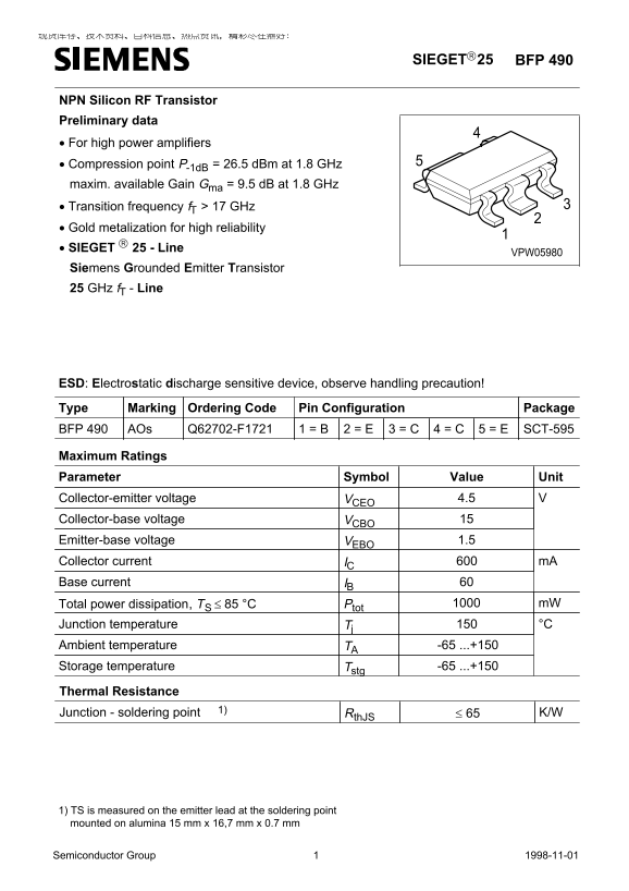
Page 1 Text Content
SIEGET25 BFP 490
NPN Silicon RF Transistor Preliminary data • For high power amplifiers • Compression point P-1d B = 26.5 d Bm at 1.8 GHz maxim. available Gain Gma = 9.5 d B at 1.8 GHz • Transition frequency f T > 17 GHz • Gold metalization for high reliability • SIEGET 25 - Line
VPW05980
Siemens Grounded Emitter Transistor 25 GHz f T - Line
ESD: Electrostatic discharge sensitive device, observe handling precaution! Type Marking Ordering Code Pin Configuration Package BFP 490 AOs Q62702-F1721 1 = B 2 = E 3 = C 4 = C SCT-5955 = E
Maximum Ratings Parameter Symbol Unit Value
4.5VCEO VCollector-emitter voltage
Collector-base voltage VCBO Emitter-base voltage VEBO 1.5 Collector current IC m A Base current IB
Total power dissipation, TS ≤ 85 °C Ptot m W
Junction temperature Tj °C Ambient temperature TA -65 ...+150 Storage temperature Tstg -65 ...+150 Thermal Resistance Junction - soldering point 1) Rth JS ≤ 65 K/W
1) TS is measured on the emitter lead at the soldering point mounted on alumina 15 mm x 16,7 mm x 0.7 mm
Semiconductor Group Sep-09-19981 Semiconductor Group 1998-11-01
Page Summary Contents For Siemens BFP 490 User Guide and Specifications (1)(1)
Manual Details
| Brand | Siemens |
|---|---|
| Pages | 8 |
| File Size | 69.86 KB |
| Published | May 31, 2026 |
Enter the captcha to get the download link:

Frequently Asked Questions
Is this RF transistor sensitive to static discharge?
Yes, it is an Electrostatic discharge (ESD) sensitive device, so handling precautions must be observed.
What is the optimum operating frequency ($f_{opt}$)?
The standard optimum operating frequency is 1.8 GHz for various parameters like Noise Figure and Power Gain.
What are the maximum continuous ratings?
The maximum collector current ($I_C$) can reach 600 mA, and the total power dissipation ($P_{tot}$) must not exceed 85 °C.
Are there limits on handling or mounting?
The transistor is designed for high reliability with gold metalization, and its package mounts on epoxy.