Siemens Intelligent Double Low-Side Switch 2 × 2 A Bipolar IC TLE 4211 Owner's Manual (1)(1) User Guide
Summary
The TLE 4211 is an intelligent double low-side switch IC engineered for demanding automotive electronic applications. It provides reliable, controlled power switching with comprehensive integrated protection, including overload detection, shorted-load safety, open load monitoring, and reverse polarity safeguarding. This technical manual offers detailed circuit specifications, pin definitions, functional block diagrams, and performance characteristics necessary for system designers. It is essential reading for electrical engineers developing high-reliability circuits that require precise logic control and maximum power stability.
Page 1 Text Content
Intelligent Double Low-Side Switch 2 × 2 A TLE 4211
Bipolar IC
Features Double low-side switch, 2 x 2 A Power limitation Overtemperature shutdown Status monitoring Shorted-load protection Reverse polarity protection Integrated clamp Z-Diodes
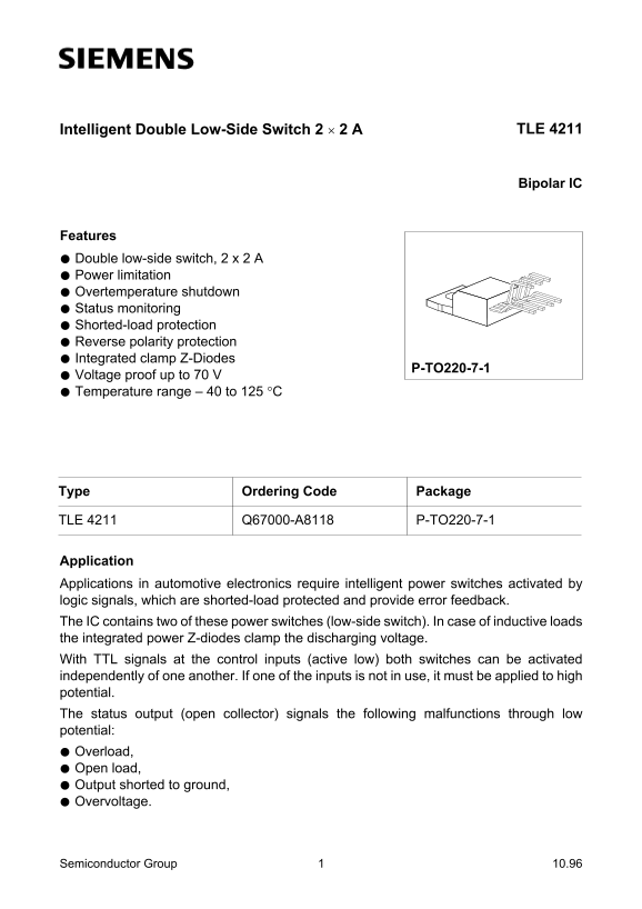
P-TO220-7-1
Voltage proof up to 70 V Temperature range – 40 to 125 °C
Type Ordering Code Package
TLE 4211 Q67000-A8118 P-TO220-7-1
Application Applications in automotive electronics require intelligent power switches activated by logic signals, which are shorted-load protected and provide error feedback. The IC contains two of these power switches (low-side switch). In case of inductive loads the integrated power Z-diodes clamp the discharging voltage. With TTL signals at the control inputs (active low) both switches can be activated independently of one another. If one of the inputs is not in use, it must be applied to high potential. The status output (open collector) signals the following malfunctions through low potential: Overload, Open load, Output shorted to ground, Overvoltage.
Semiconductor Group 10.96
Page Summary Contents For Siemens Intelligent Double Low-Side Switch 2 × 2 A Bipolar IC TLE 4211 Owner's Manual (1)(1) User Guide
Manual Details
| Brand | Siemens |
|---|---|
| Pages | 13 |
| File Size | 393.14 KB |
| Published | June 01, 2026 |
Enter the captcha to get the download link:

Frequently Asked Questions
How must the switches be activated using control signals?
They are activated when TTL-compatible logic signals applied to IN1 and IN2 reach a low potential (active low).
What status output indicates system malfunctions?
The open collector status output monitors issues like Overload, Open load, or Shorted output to ground by switching to low potential.
Is the device protected against inductive load spikes?
Yes, integrated power Z-diodes clamp positive voltage peaks that occur during the switching of inductive loads.
What is the maximum current capacity for grounding wiring?
The grounding must be designed for a maximum short-circuit current of 6 x 3.5 A.