Siemens BAT 14-099 Data Sheet User Guide
Summary
This high-performance dual Schottky Diode is an ideal component for demanding RF applications, such as mixing circuits up to 12 GHz, requiring a stable, low noise figure. The technical manual provides comprehensive data crucial for circuit designers, including full maximum ratings, detailed electrical characteristics across varying frequencies (DC to 150+ GHz), and current/voltage stability curves. It is essential documentation for RF and power electronics engineers developing reliable high-frequency mixed signal or monitor systems.
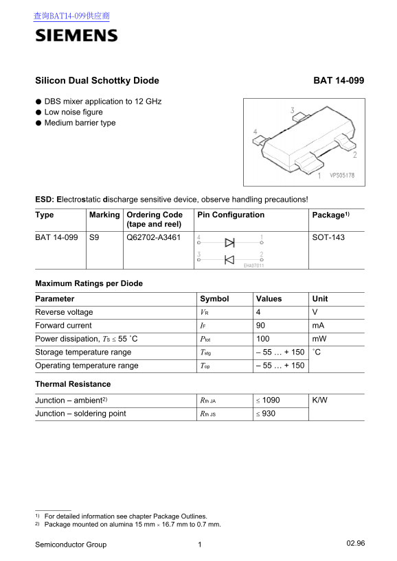
Page 1 Text Content
查询BAT14-099供应商
Silicon Dual Schottky Diode BAT 14-099
DBS mixer application to 12 GHz Low noise figure Medium barrier type
ESD: Electrostatic discharge sensitive device, observe handling precautions! Type Marking Ordering Code Package1)Pin Configuration
(tape and reel)
BAT 14-099 Q62702-A3461S9 SOT-143
Maximum Ratings per Diode Parameter Symbol Values Unit Reverse voltage VR Forward current IF m A Power dissipation, TS ≤ 55 ˚C Ptot m W
Storage temperature range Tstg – 55 … + 150 ˚C Operating temperature range – 55 … + 150
Thermal Resistance
Junction – ambient2) Rth JA ≤ 1090 K/W
Junction – soldering point Rth JS ≤ 930
1) For detailed information see chapter Package Outlines. 2) Package mounted on alumina 15 mm 16.7 mm to 0.7 mm.
Semiconductor Group 02.96
Page Summary Contents For Siemens BAT 14-099 Data Sheet User Guide
Manual Details
| Brand | Siemens |
|---|---|
| Pages | 4 |
| File Size | 81.05 KB |
| Published | June 06, 2026 |
Enter the captcha to get the download link:

Frequently Asked Questions
Is special handling required due to static electricity?
Yes, this is an ESD (Electrostatic discharge sensitive device), and users must observe appropriate handling precautions.
What are the allowed operational temperature ranges for the diode?
The operating temperature range is from -55°C up to +150°C.
What material should I mount this diode on?
It must be mounted on alumina measuring 15 mm × 16.7 mm and having a thickness of 0.7 mm.
What is the maximum power dissipation limit during soldering?
The total power dissipation ($P_{tot}$) rating for soldering must not exceed 100 mW.