ROHM DTC123EM DTC123EE DTC123EKA DTC123EUA User Manual
Summary
These compact digital transistors are designed for switching, interfacing, and driving applications requiring a robust output stable up to 50V. Featuring built-in bias resistors, this series significantly simplifies circuit design by eliminating the need for external input components. The manual provides electrical characteristics, performance curves, maximum ratings, and detailed guidance on integrating the transistor into complex inverters and driver circuits. Ideal for electronics engineers requiring high reliability and ease of use in modern circuit development.
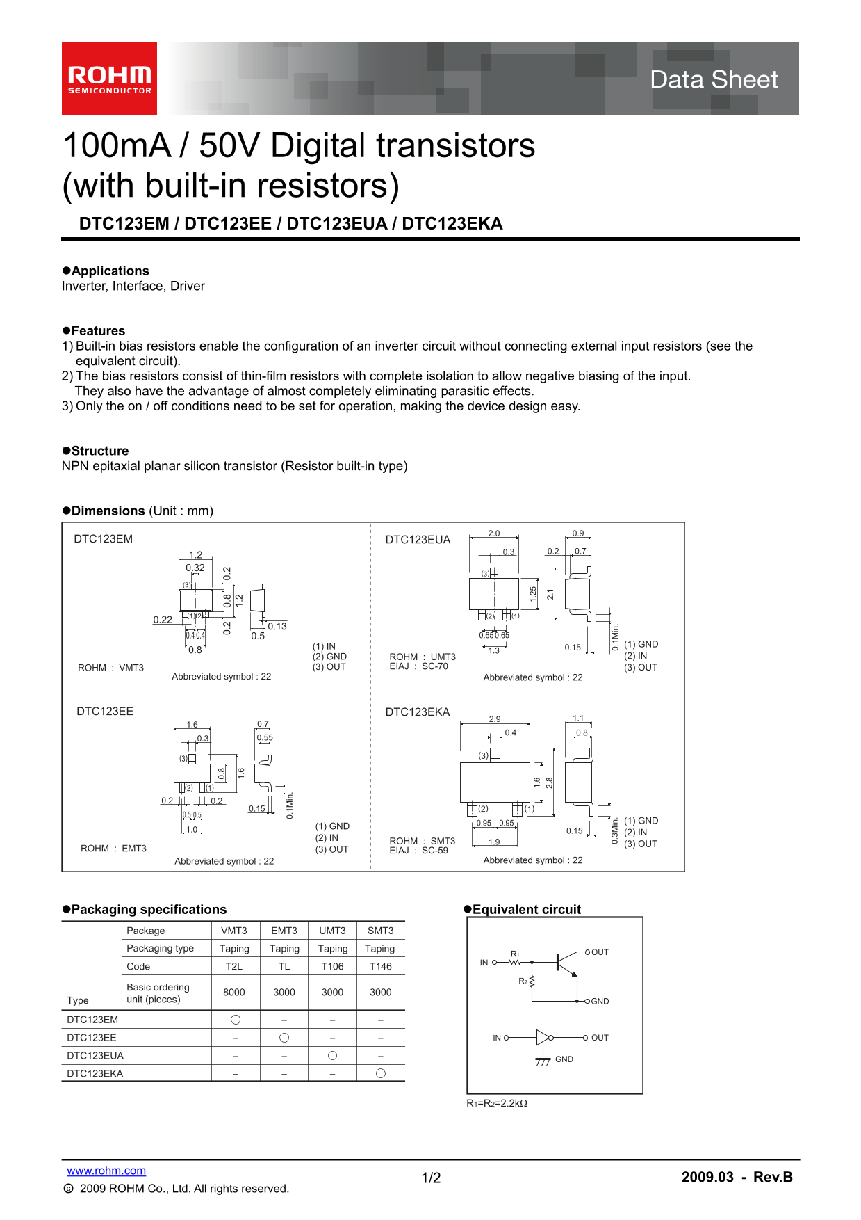
Page 1 Text Content
100m A / 50V Digital transistors (with built-in resistors)
DTC123EM / DTC123EE / DTC123EUA / DTC123EKA 0. 0. 0.
Applications Inverter, Interface, Driver 0. 1M in
Features 1) Built-in bias resistors enable the configuration of an inverter circuit without connecting external input resistors (see the equivalent circuit). 2) The bias resistors consist of thin-film resistors with complete isolation to allow negative biasing of the input. They also have the advantage of almost completely eliminating parasitic effects. 3) Only the on / off conditions need to be set for operation, making the device design easy.
Structure NPN epitaxial planar silicon transistor (Resistor built-in type)
Dimensions (Unit : mm)
DTC123EM 1.
DTC123EUA
(2)(1) 0. 3M in (2) (1) 0. 1M in
(1) IN (1) GND
(2) GND ROHM : UMT3 (2) IN
(3) OUTROHM : VMT3 EIAJ : SC-70 (3) OUT
Abbreviated symbol : 22 Abbreviated symbol : 22
DTC123EE DTC123EKA
0.95 0.95 (1) GND
(1) GND
(2) IN
(2) IN
1.9 (3) OUTROHM : SMT3
(3) OUTROHM : EMT3 EIAJ : SC-59
Abbreviated symbol : 22 Abbreviated symbol : 22
Packaging specifications Equivalent circuit
Package VMT3 UMT3EMT3 SMT3
Packaging type Taping Taping Taping Taping
R1 OUT
Code T2L TL T106 T146
Basic ordering Type unit (pieces) GND
DTC123EM
DTC123EE IN OUT
DTC123EUA
DTC123EKA
1/2 www.rohm.com 2009.03 - Rev.B
○c 2009 ROHM Co., Ltd. All rights reserved.
Page Summary Contents For ROHM DTC123EM DTC123EE DTC123EKA DTC123EUA User Manual
Manual Details
| Brand | ROHM |
|---|---|
| Pages | 3 |
| File Size | 162.63 KB |
| Published | July 16, 2026 |
Enter the captcha to get the download link:

Frequently Asked Questions
How do these transistors simplify inverter circuit design?
They feature built-in bias resistors, which eliminates the need for connecting external input resistors and allows configuration of an inverter circuit.
What are the critical operating limits for this device?
The absolute maximum rating specifies a Supply Voltage ($V_{CC}$) limit of 50 V and an Input Voltage ($V_{IN}$) range of -10 to +12 V.
What is the approximate DC current gain (GI)?
The typical DC current gain (GI) stated in the electrical characteristics table is listed as achieving a minimum of 20.
Are these components suitable for mission-critical systems?
No, they are not designed for equipment requiring extremely high reliability, such as medical instruments or aerospace machinery. Safety measures like derating must be implemented.