ROHM 2SA1952 User Guide Manual
Summary
The 2SA1952 is a high-speed NPN switching transistor engineered for robust power switching applications. Featuring fast transition times and low saturation voltage, it offers superior performance in demanding circuits while complementing compatible devices. This comprehensive datasheet provides all necessary information for designers, including absolute maximum ratings, detailed operational curves, collector output capacitance ($C_{ob}$), transient parameters (turn-on/fall times), and DC current gain ($h_{FE}$). Use this resource to reliably select the perfect component for your power electronics designs.
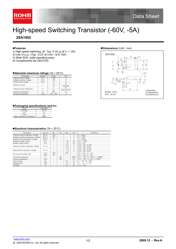
Page 1 Text Content
High-speed Switching Transistor (-60V, -5A) 2SA1952
Features Dimensions (Unit : mm) 1) High speed switching. (tf : Typ. 0.15 s at IC = -3A)
2) Low VCE(sat). (Typ. -0.2V at IC/IB= -3/-0.15A) 2SA1952
3) Wide SOA. (safe operating area) 4) Complements the 2SC5103.
Absolute maximum ratings (Ta = 25C) C0.50.
Parameter Symbol Limits Unit
Collector-base voltage VCBO −100
Collector-emitter voltage VCEO −60
0.8Min.
Emitter-base voltage VEBO −5
Collector current IC
−10 A(Pulse) 2.5
Collector power dissipation PC 9.5
W(Tc=25°C)
(1) Base(Gate)
Junction temperature Tj °C ROHM : CPT3
(2) Collector(Drain)
Storage temperature Tstg −55~+150 °C
EIAJ : SC-63 (3) Emitter(Source)
Packaging specifications and h FE Type 2SA1952
Package CPT3
h FE 1.
Code TL 0.
Basic ordering unit (pieces)
Electrical characteristics (Ta = 25C)
Parameter Symbol Min. Typ. Max. Unit Conditions
Collector-base breakdown voltage BVCBO −100 IC = −50μA
Collector-emitter breakdown voltage BVCEO −60 IC = −1m A
Emitter-base breakdown voltage BVEBO −5 IE = −50μA
Collector cutoff current ICBO −10 μA VCB = −100V
IEBO −10 μA VEB = −5V 5.
Emitter cutoff current 2. 30.
−0.3 IC/IB= −3A/ −0.15A
Collector-emitter saturation voltage VCE(sat) 6.
−0.5 IC/IB= −4A/ −0.2A −1.2 IC/IB= −3A/ −0.15A
Base-emitter saturation voltage VBE(sat)
−1.5 IC/IB= −4A /−0.2A
h FE1 VCE = −2V , IC = −1A
DC current transfer ratio
h FE2 VCE = −2V , IC = −3A Transition frequency f T MHz VCE = −10V , IE = 0.5A , f = 30MHz Output capacitance Cob p F VCB = −10V , IE = 0A , f = 1MHz Turn-on time ton 0.3 μs IC = −3A , RL = 10Ω Storage time tstg 1.5 μs IB1 = −IB2 = −0.15A Fall time tf 0.3 μs VCC −30V
www.rohm.com
1/2 2009.12 - Rev.A
○c 2009 ROHM Co., Ltd. All rights reserved.
Page Summary Contents For ROHM 2SA1952 User Guide Manual
Manual Details
| Brand | ROHM |
|---|---|
| Pages | 3 |
| File Size | 158.86 KB |
| Published | June 18, 2026 |
Enter the captcha to get the download link:

Frequently Asked Questions
What is the typical switching time of this transistor?
The typical switching time ($t_f$) is 0.15 µs when operating at an IC = −3A.
What measure should be taken when circuit designing with these components?
Users must implement safety measures such as derating, redundancy, and fail-safe designs to guard against physical injury or fire.
How is this transistor typically required in a pair arrangement?
It complements the 2SC5103 component.
What is the maximum collector power dissipation (Pc) rating at standard conditions?
The collector power dissipation ($P_C$) is rated up to 1 W under specified testing temperatures.