ROHM 2SD1782K User Manual
Summary
This technical manual provides comprehensive specifications for the 2SD1782K NPN power transistor, an ideal component for robust electrical circuit design. Featuring a high 80V maximum collector-emitter voltage and low saturation voltage (VCEsat=0.2V typ.), this solid-state component is designed to provide reliable current switching up to 0.5A. Engineers can utilize the detailed data sheets, including full electrical characteristics, operating curves, and absolute ratings, to integrate the transistor into diverse electronic applications such as communication or audio equipment circuits.
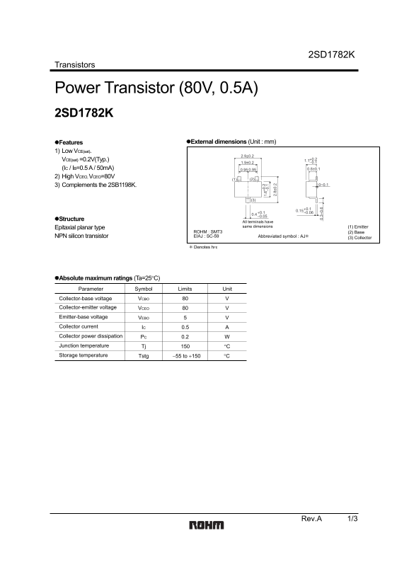
Page 1 Text Content
2SD1782K
Transistors
Power Transistor (80V, 0.5A) 2SD1782K
Features External dimensions (Unit : mm)
1) Low VCE(sat).
VCE(sat) =0.2V(Typ.) +0.2 1.1 1.9±0.2 −0.1
(IC / IB=0.5 A / 50m A) 0.95 0.95 0.8±0.1
2) High VCEO, VCEO=80V
3) Complements the 2SB1198K. 0~0.1
Structure
All terminals have same dimensions (1) Emitter
Epitaxial planar type
ROHM : SMT3 (2) Base NPN silicon transistor EIAJ : SC-59 Abbreviated symbol : AJ∗
(3) Collector
∗ Denotes h FE
Absolute maximum ratings (Ta=25°C) Parameter Symbol Limits Unit Collector-base voltage VCBO Collector-emitter voltage VCEO Emitter-base voltage VEBO
Collector current 0.5IC Collector power dissipation PC 0.2 Junction temperature Tj °C Storage temperature Tstg −55 to +150 °C
Rev.A 1/3
Page Summary Contents For ROHM 2SD1782K User Manual
Manual Details
| Brand | ROHM |
|---|---|
| Pages | 4 |
| File Size | 75.74 KB |
| Published | June 15, 2026 |
Enter the captcha to get the download link:

Frequently Asked Questions
What is the typical collector-emitter saturation voltage VCE(sat)?
The datasheet lists a low VCE(sat) of 0.2V (Typ.) when IC/IB=0.5 A / 50mA.
Is this transistor suitable for life-critical equipment like aerospace machinery?
No, if the device is intended for extremely high reliability or where malfunction endangers human life, you must consult a sales representative before use.
What are the absolute maximum ratings for voltage and power dissipation?
The absolute limits include VCB(O) up to 80V, VCEO up to 80V, and PC (Collector power dissipation) up to 0.2W.
Does this transistor complement other components?
Yes, the structure notes that it complements the 2SB1198K.