# A B C D E F G H I J K L M N O P Q R S T U V W X Y Z

ROHM BU21008MUV datasheet user manual

Summary

This advanced capacitive sensor controller IC provides robust human-machine interaction for portable electronics. It features 16 sensing channels, integrated gesture recognition, and PWM control for LED indicators. This manual details the complete technical specifications, including the ADC operation, power management logic, and digital interface methods. Ideal for designers creating consumer devices, mobile phones, or smart automation equipment requiring sophisticated, low-power capacitive switching solutions.
📄 Preview PAGE OF 17

Page 1 Text Content

Capacitive Sensor Control IC Series

Capacitive Sensor Switch Control IC

No.09048EBT04

BU21008MUV

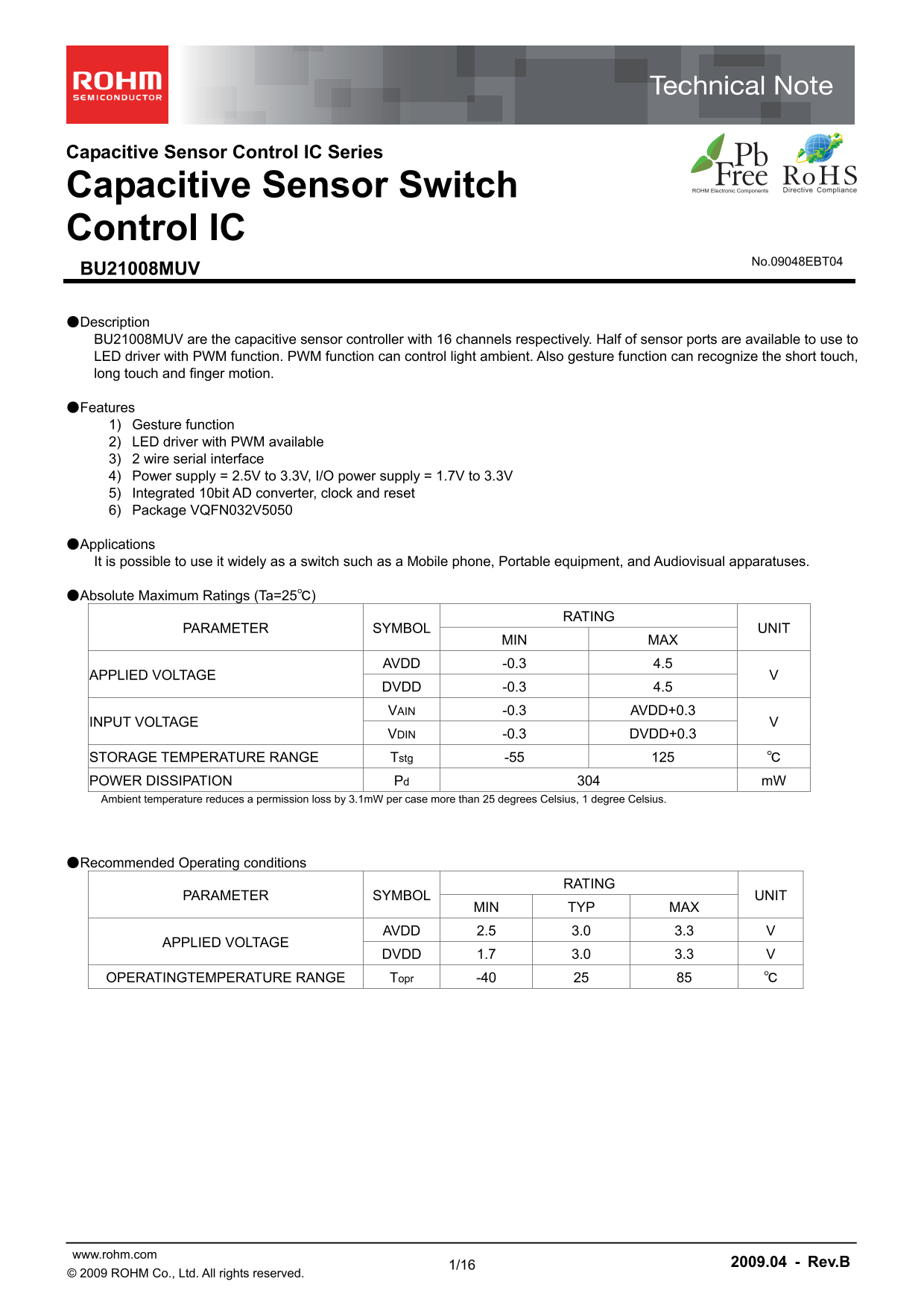
●Description BU21008MUV are the capacitive sensor controller with 16 channels respectively. Half of sensor ports are available to use to LED driver with PWM function. PWM function can control light ambient. Also gesture function can recognize the short touch, long touch and finger motion.

●Features 1) Gesture function 2) LED driver with PWM available 3) 2 wire serial interface 4) Power supply = 2.5V to 3.3V, I/O power supply = 1.7V to 3.3V 5) Integrated 10bit AD converter, clock and reset 6) Package VQFN032V5050

●Applications It is possible to use it widely as a switch such as a Mobile phone, Portable equipment, and Audiovisual apparatuses.

●Absolute Maximum Ratings (Ta=25℃)

RATING

PARAMETER SYMBOL UNIT

MIN MAX

AVDD -0.3 4.5

APPLIED VOLTAGE

DVDD -0.3 4.5 VAIN -0.3 AVDD+0.3

INPUT VOLTAGE

VDIN -0.3 DVDD+0.3

STORAGE TEMPERATURE RANGE Tstg -55 125 ℃ POWER DISSIPATION Pd 304 m W Ambient temperature reduces a permission loss by 3.1m W per case more than 25 degrees Celsius, 1 degree Celsius.

●Recommended Operating conditions

RATING

PARAMETER SYMBOL UNIT

MIN TYP MAX

AVDD 2.5 3.0 3.3 V

APPLIED VOLTAGE

DVDD 1.7 3.0 3.3 V

OPERATINGTEMPERATURE RANGE Topr -40 25 85 ℃

www.rohm.com 2009.04 - Rev.B

© 2009 ROHM Co., Ltd. All rights reserved.

Page Summary Contents For ROHM BU21008MUV datasheet user manual

Page 1 Capacitive Sensor Control IC Series Capacitive Sensor Switch Control IC No.09048EBT04 BU21008MUV ●Description BU21008MUV are the capacitive sensor controller with 16 channels respectively. Half of sen...
Page 2 BU21008MUV Technical Note ●Electrical characteristics(Especially, Topr=25℃ and AVDD=DVDD=0 as long as it doesn't specify it.) RATING PARAMETER SYMBOL UNIT Condition MIN TYP MAX H INPUT VOLTAGE VIHIO D...
Page 3 BU21008MUV Technical Note ●Block Diagram, Pin configuration AVDD DVDD Sensor I/F、 DVSS MODE[1] Data correction and ST CV translate ADC SI N[ LE D[ 5] making to format SIN[15:0] circuit DVDD MODE[0] LK...
Page 4 BU21008MUV Technical Note ●Pin Description Pin Supply Reset I/O Name I/O Function Note No. Reference Level Pad 1 SIN4 AIn sensor input4 - AVDD "Hi-Z" sensor input 5 sensor input , LED drive ...
Page 5 BU21008MUV Technical Note ●I/O Circuit ①CMOS INPUT ②CMOS Schmitt INPUT ③CMOS OUTPUT PADCIN PADCIN ④CMOS 3stute OUTPUT with ⑤CMOS Schmitt INOUT ANALOG-SW www.rohm.com 2009.04 - Rev.B © 2009 ROHM Co., L...
Page 6 BU21008MUV Technical Note ●HOST I/F ・2 wire serial, BUS (Pin configuration, MODE[1:0]=00b) Slave mode only Slave Address = 5Ah,5Bh selection possible. Normal (Normal mode. 100k Hz Transfer rate) Fs mo...
Page 7 BU21008MUV Technical Note ●Register map Address Register name R/W Length Explanation 1*h SENS_DATA R 1byte / channel Sensor output data. One for each channel. 32h, 33h BTN R 2byte Button On/Off. 35h B...
Page 8 BU21008MUV Technical Note 【1*h : Sensor Output Data】 Name: SENS_DATA Address: 1* h (one byte per sensor channel) Description: The sensor output that converts to 10bit. Scaling, offsets and filtering (...
Page 9 BU21008MUV Technical Note 【62h : Gesture Direction Judgment】 Name: GES_DIR rig ht ne ss rig ht ne ss Address: 62h Description: Gesture direction judgment DIR_A : gesture direction A 0x E3(GES_CTL) ref...
Page 10 BU21008MUV Technical Note 【E1h : PWM Clock Setting】 Name: FEAD_CLK Address: E1h Description: This register defines the divide ratio of the clock used for PWM. This also relates to the fade-in and fade...
Page 11 BU21008MUV Technical Note 【E4h : Gesture Clock Setting】 Name: GES_CLK Address: E4h Description: This register allows setting of the time base for the gesture detection. It sets a divide ratio of the c...
Page 12 BU21008MUV Technical Note 【EFh : Setting Done, Detect Start】 Name: DONE Address: EFh Description: This register should be written to following register updates. Bit7 Bit6 Bit5 Bit4 Bit3 Bit2 Bit1 Bit0...
Page 13 BU21008MUV Technical Note 【F6h : Sampling Interval and Number of Samples Used for Button Press】 Name: TIMES Address: F6h Description: Defines the sampling interval and number of samples required to re...
Page 14 BU21008MUV Technical Note 【FBh : Gain Setting, Filter Function】 Name: GAIN_FILTER Address: FBh Description: Gain adjustment and setting of noise filter function. GAIN[2:0] : gain setting : It uses it ...
Page 15 BU21008MUV Technical Note ●Operation mode This IC has a normal mode, idle mode and a shutdown mode as states of operation. 【Normal mode】 This is the normal operation of the device. Output pin INT=&quo...
Page 16 BU21008MUV Technical Note ●Ordering part number Part No Part No Package Packaging and forming specification 1. 0M MUV : VQFN032V5050 E2:Embossed tape and reel 5. ±0 .1 VQFN032V5050 <Tape and Reel i...
Page 17 Notice No copying or reproduction of this document, in part or in whole, is permitted without the consent of ROHM Co.,Ltd. The content specified herein is subject to change for improvement without not...

Manual Details

Brand ROHM
Pages 17
File Size 677.81 KB
Published July 15, 2026
2 views

Enter the captcha to get the download link:

captcha

Frequently Asked Questions

What types of touch gestures can the capacitive sensor recognize?

The gesture function supports recognizing short touch, long touch, and finger motion.

How does this control IC interface with a host system?

It utilizes a two-wire serial interface for communication purposes.

What are the recommended voltage ranges for AVDD and DVDD?

AVDD should operate between 2.5V and 3.3V, while DVDD should operate between 1.7V and 3.3V.

Can this device be used in life-critical systems (e.g., medical or aerospace)?

No, it is not designed for equipment requiring extremely high levels of reliability where failure poses a threat to human life.